
Whole-line scanning type laser projection display device

A technology of laser projection and display devices, which is applied in the direction of using projection devices, image reproducers, projection devices, optics, etc., can solve the problem that the color gamut coverage of bulb projectors is less than 30%, complex two-dimensional scanning devices, burns to human eyes or Skin and other problems, to achieve the effect of delicate picture, simple optical structure and high safety

Inactive Publication Date: 2016-08-24
武阳
View PDF6 Cites 4 Cited by
  • Summary
  • Abstract
  • Description
  • Claims
  • Application Information

AI Technical Summary

Problems solved by technology

Lamp projectors have less than 30% color gamut coverage
Laser point-by-point scanning projection imaging technology can have very high resolution, but the power of the laser beam is very high. Once the beam stops scanning and does not move, it is easy to cause fire and burn human eyes or skin; the two-dimensional scanning device is also relatively complicated.

Method used


Image

  • Whole-line scanning type laser projection display device
  • Whole-line scanning type laser projection display device
  • Whole-line scanning type laser projection display device

Examples


no. 1 example

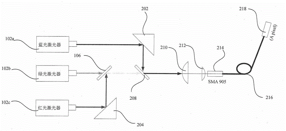
[0051] Please refer to figure 1 , which is a schematic diagram of an optical path formed by one pixel of the full-line scanning laser display device of the present application. Such as figure 1 As shown, the laser generator module 100 includes a red laser 102c, a green laser 102b and a blue laser 102a, a first dichroic mirror 106 and a second dichroic mirror 208, a first right-angle corner 204 and a second right-angle corner 202. The arrangement of the above optical devices is as follows figure 1 shown.

[0052] The red laser beam emitted by the red laser 102c is reflected by the first right-angle prism 204, and the direction of propagation is turned by 90° to irradiate on the first dichroic mirror 106; the first dichroic mirror 106 transmits green light and reflects red light; carefully Adjusting the distance between the first right-angled corner 204 and the red laser (that is, moving the first right-angled corner 204 in the horizontal direction), and rotating the firs...

no. 2 example

[0064] In this embodiment, the scanning device is the same as the above embodiment, except that the way of forming a single pixel is different. Please refer to Figure 6 , which is a schematic diagram of the optical path for forming a single pixel in the second embodiment of the scanning laser display device of the present application. In this embodiment, the laser generator module includes red, green, and blue three-color lasers (102c, 102b, 102a), and collimation elements (210a, 210b, 210c; 212a , 212b, 212c);

[0065] The light guide device includes an optical fiber corresponding to each laser, and the coupling end of each optical fiber is provided with a coupling joint SMA905 or an FC joint as the laser coupling interface; the coupling joint is arranged on the light guide In the collimated optical path of the laser corresponding to the fiber, and facing the incoming light direction, it is used to receive the laser beam emitted by the corresponding laser; bonded together...

no. 3 example

[0069] In this embodiment, the implementation of the monochrome pixel is basically the same as that of the above-mentioned second embodiment, the difference is that the light-emitting end surface of the optical fiber corresponding to one of the blue lasers 103b is provided with a phosphor coating, such as Figure 10 The phosphor coating shown in , was used to generate green light under blue laser excitation. Other aspects of this embodiment are the same as the above-mentioned second embodiment. The advantage of this embodiment is that the image speckle is very weak.


PUM


Abstract

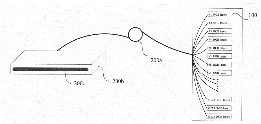
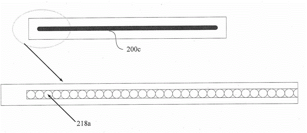
The invention discloses a whole-line scanning type laser projection display device. The whole-line scanning type laser projection display device comprises a light source assembly, a one-dimensional imaging device, a scanning device a control device and a projection lens, wherein the light source assembly comprises a plurality of laser generator modules, and each laser generator module is used for generating laser corresponding to a single pixel; the one-dimensional imaging device comprises a plurality of light guide apparatuses, and a laser generator module laser coupling interface member arranged at a coupling end of each light guide apparatus; light emitting ends of the light guide apparatuses are in one-dimensional arrangement along a first direction; the scanning device is provided with at least one reflecting surface, the scanning device is arranged in a light path of laser emitted from the light emitting ends, and the projection lens forms an image of the light emitting ends in one-dimensional arrangement along the first direction onto a screen; and the control device is connected with the light source assembly, the scanning device is provided with a rotating shaft parallel to the first direction, and the projected one-dimensional emergent light is enabled to realize scanning in a second direction perpendicular to the first direction when the scanning device rotates around its rotating shaft.

Description

[0001] This application claims the priority of the Chinese patent application with the application number 201410490118.7 and the title of the invention "a full-line scanning laser projection display device" submitted to the China Patent Office on September 23, 2014, the entire contents of which are incorporated herein by reference In this application. technical field [0002] The present application relates to the technical field of laser display, in particular to a full-line scanning laser projection display device. Background technique [0003] 83% of human information is obtained through vision, while the sum of information obtained through hearing, smell, taste and touch only accounts for 27%, which shows the importance of display devices for human information acquisition. In 1897, Braun invented the CRT (Cathode-Ray-Tube, cathode ray tube), and mankind has since entered the era of electronic display. In the following 100 years, human beings successively invented variou...

Claims


Application Information

Patent Timeline
Patent Type & Authority Applications(China)
IPC IPC(8): G03B21/20H04N9/31
Inventor 武阳
Owner 武阳
Learn More