Method and apparatus for encoding and decoding of video streams

Inactive Publication Date: 2008-06-26
ON DEMAND MICROELECTRONICS
View PDF14 Cites 55 Cited by
  • Summary
  • Abstract
  • Description
  • Claims
  • Application Information

AI Technical Summary

Benefits of technology

[0038]In another exemplary embodiment, the present invention is a video decoding apparatus coupled to receive an encoded input video stream having a sequence of coded frames. The apparatus includes a divider circuit configured to divide the input video stream into a plurality of single coded frames and transfer at least one of the plurality of single coded frames to a plurality of decoding units and a plurality of shared information memory units. Each of the plurality of shared information memory units is coupled to and associated with at least one of the plurality of decoding units. Each of the plurality of

Problems solved by technology

The temporal prediction of frames is theoretically lossless, but such prediction can lead to a serious degradation in video quality when transmission errors occur and these transmission errors get replicated in consecutive frames.
For example, if an error occurs in some content and subsequent transmissions rely on the content to predict future data, the error can multiply causing widespread degradation of the video signal.
Often, the most obvious distortion or artifacts in a video stream are the appearance of square or rectangular blocks in the decoded frame.
Although state-of-the-art video compression standards provide high compression rates and even allow one to maintain high picture quality, the compression standards require a lot of computational resources to encode the frames with a reasonable size and quality.
However, common standards for video encoding and decoding strongly restrict the degree of parallelization.
Therefore, one of the basic problems in video encoder and decoder development is to find the best way to split the encoding task of a video stream for parallel processing.
However, some disadvantages of known methods are asymmetric usage of the parallel processing units, reduced compression efficiency, and complex handling of boundary regions between parallel-processed data blocks.
However, strong dependencies exist between successive macroblocks.
Further, macroblock parallelism r

Method used


Image

  • Method and apparatus for encoding and decoding of video streams
  • Method and apparatus for encoding and decoding of video streams
  • Method and apparatus for encoding and decoding of video streams

Examples


Embodiment Construction

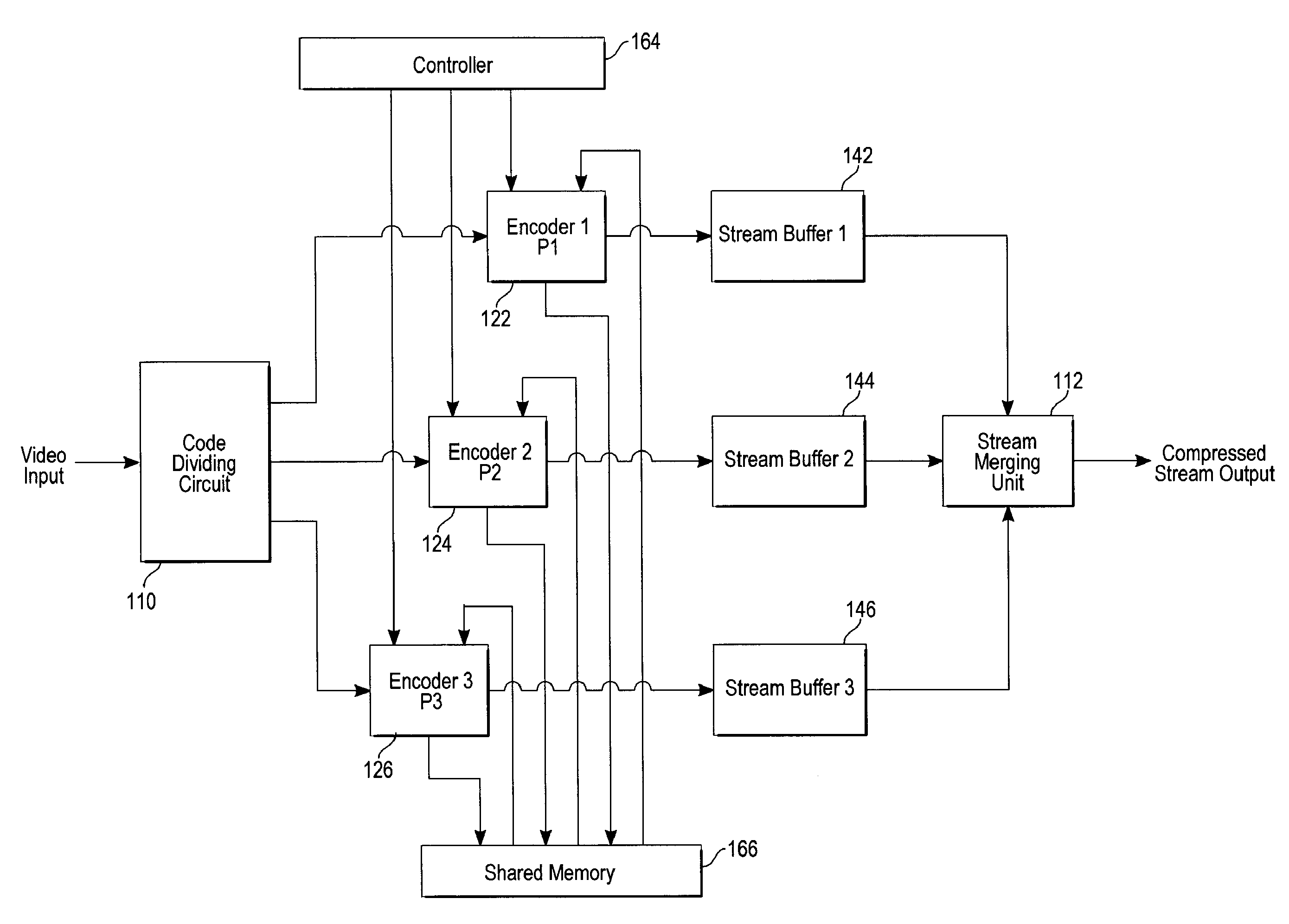
[0056]In the following description, a new method and apparatus to encode and / or decode a video stream exploiting frame-level parallelism is disclosed. The frames of the video stream are encoded and / or decoded using M processing units where each processing unit processes one different frame at a time. Each processing unit can write a reconstructed frame to a frame buffer. A subsequent processing unit can use the reconstructed frame from that frame buffer as a reference frame. Hence, the processing units are connected via the frame buffers. The frame processing occurs time-displaced and can start when sufficient input data are available and, if necessary, if sufficient data of the reconstructed previous frame which was calculated in a previous stage are available.

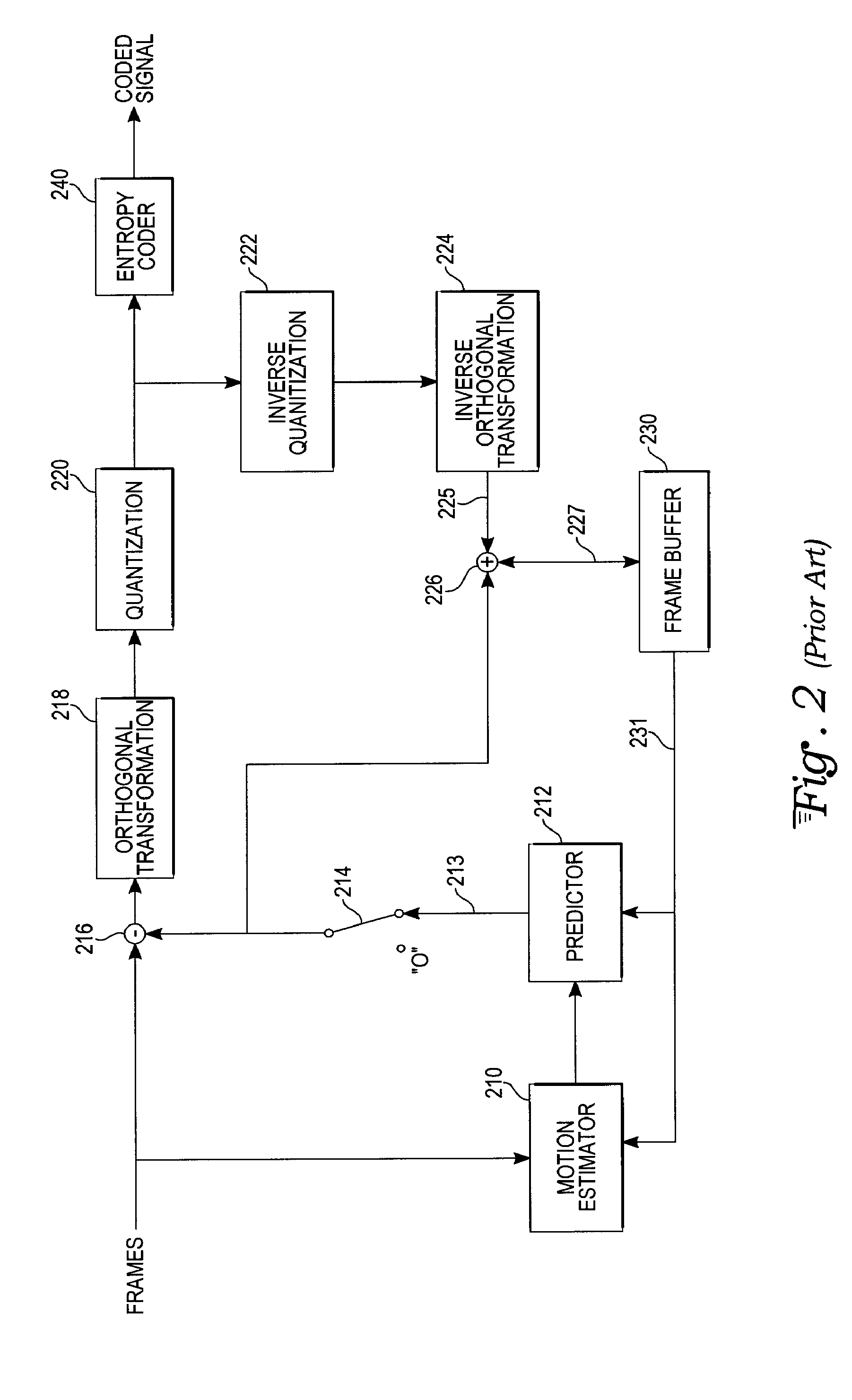
[0057]As explained above with reference to FIG. 2, the frame buffer 230 in known architectures stores at least two frames: the reconstructed previous frame 231 and the reconstructed current frame 227. The method and apparatus...


PUM


Abstract

A method and processor to encode and/or decode a video stream exploiting frame-level parallelism. Frames of the video stream are encoded and/or decoded using M processing units where each processing unit processes one different frame at a time. Each processing unit writes the reconstructed frame to a frame buffer. A processing unit can start the encoding and/or decoding process once sufficient data of the previous reconstructed frame are available.

Description

CROSS-REFERENCE TO RELATED APPLICATION[0001]This application claims priority from U.S. Provisional Patent Application Ser. No. 60 / 871,141 entitled “Method and Apparatus for Encoding and Decoding of Video Streams,” filed Dec. 21, 2006 and which is hereby incorporated by reference in its entirety.TECHNICAL FIELD[0002]The invention relates in general to digital video encoding and decoding and in particular to digital video encoding and decoding which exploits frame-level parallelism.BACKGROUND[0003]Video compression is a process where, instead of transmitting a full set of data for each picture element or pixel on a display for each frame, a greatly reduced amount of data can be coded, transmitted, and decoded to achieve the same perceived picture quality. Generally, a pixel is a small dot on a display wherein hundreds of thousands of pixels make up the entire display. A pixel can be represented in a signal as a series of binary data bits. Compression of data often utilizes the assumpt...

Claims


Application Information

Patent Timeline
IPC IPC(8): H04N7/26
CPCH04N19/172H04N19/436H04N19/61
Inventor SCHREIER, RALF MICHAELSEITNER, FLORIAN
Owner ON DEMAND MICROELECTRONICS
Why Eureka
Try Eureka