
Selectable diaphragm condenser microphone

a diaphragm condenser and microphone technology, applied in the field of condenser microphones, can solve the problems of high cost, from inexpensive to very expensiv

Active Publication Date: 2008-06-26
MARSHALL ELECTRONICS
View PDF9 Cites 37 Cited by
  • Summary
  • Abstract
  • Description
  • Claims
  • Application Information

AI Technical Summary

Benefits of technology

"The present invention is a condenser microphone with a unique design that allows for independent control of two different sound reproduction characteristics. The microphone has a back plate with a polarizing voltage that is activated based on the user's selection of a diaphragm. The microphone also includes LED lights behind the grill to indicate which diaphragm is activated. The dual diaphragm arrangement is mounted on a standard microphone body and includes conventional electronics for connection to an associated piece of audio equipment producing phantom power. The invention provides a microphone that can produce warm and lush sounds or bright and airy sounds, depending on the user's needs. The microphone is easy to use and provides a visual indication of the type of sound output produced by the microphone."

Problems solved by technology

Condenser microphones produce high quality audio signals and are a popular choice in laboratory and studio recordings and range in cost from inexpensive to very expensive.

Method used


Image

  • Selectable diaphragm condenser microphone
  • Selectable diaphragm condenser microphone
  • Selectable diaphragm condenser microphone

Examples


Embodiment Construction

[0029]The detailed embodiment of the present invention is disclosed herein. It should be understood, however, that the disclosed embodiment is merely exemplary of the invention, which may be embodied in various forms. Therefore, the details disclosed herein are not to be interpreted as limiting, but merely as the basis for the claims and as a basis for teaching one skilled in the art how to make and / or use the invention.

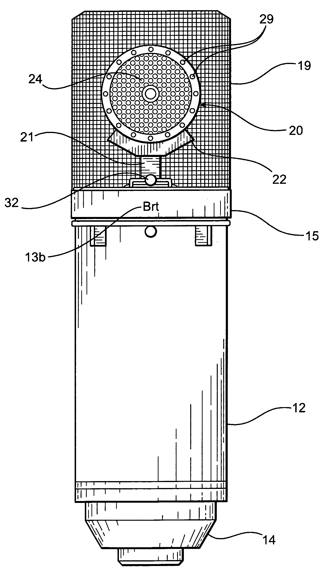
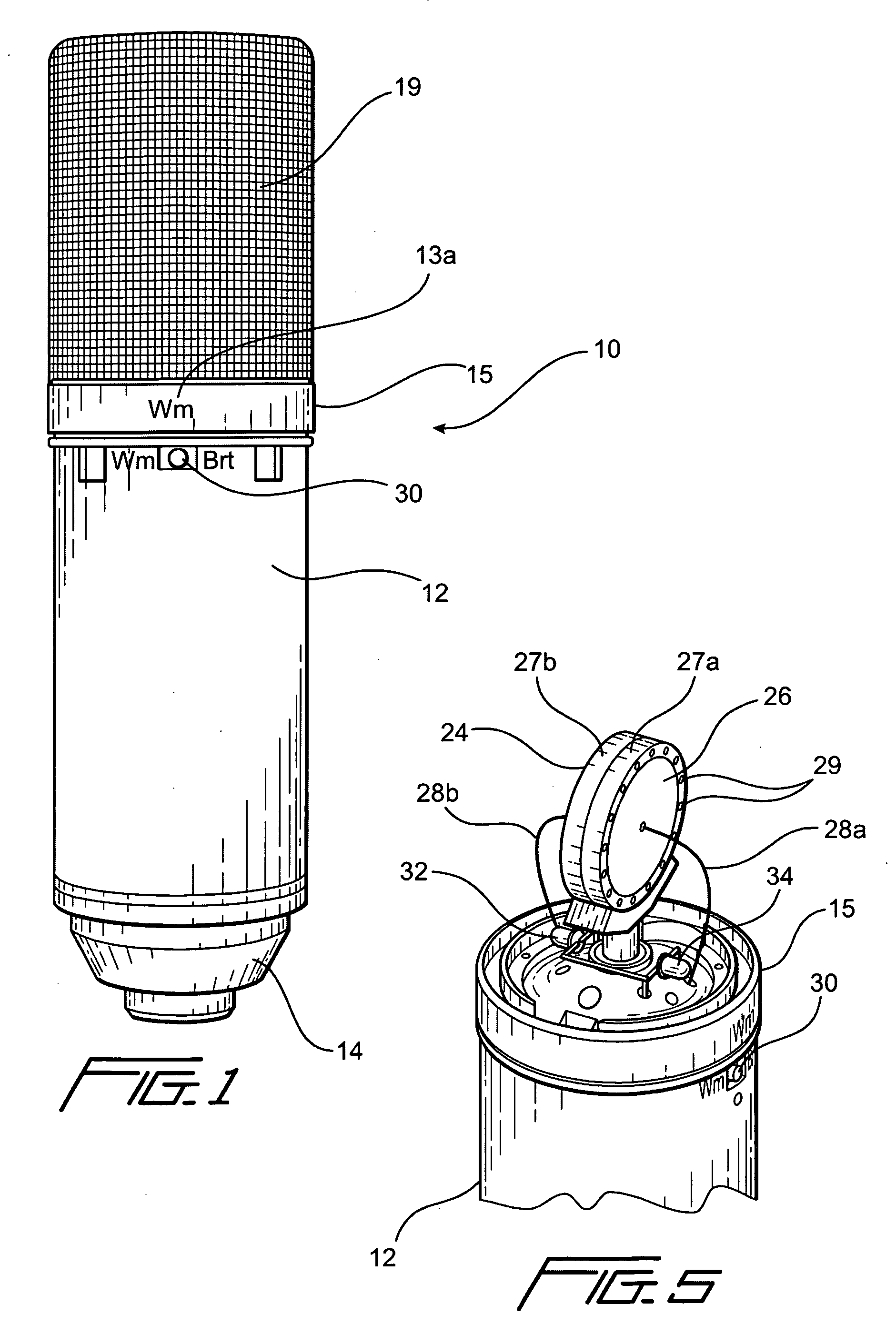
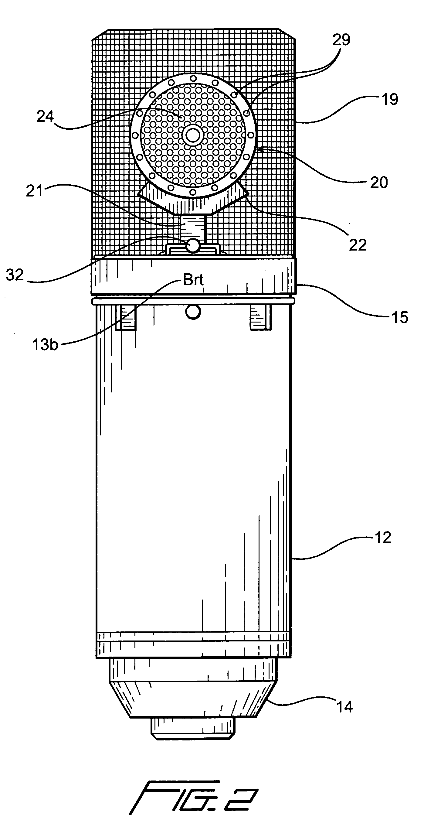
[0030]Referring to the drawings, a condenser microphone 10 includes a cylindrical body 12 having a bottom ring 14 and a top closure 15 secured thereto. The body 12 can be made of various plastics, however, metal is the preferred material. A female XLR cable connector 16 is mounted in the bottom ring 14 for attachment to a male XLR cable connector at the end of a cable (not shown) going to an amplifier, power source or other audio equipment used to reproduce the sound. That is, the cable functions to connect the microphone 10 to an input on an electronic sound system ...


PUM


Abstract

A condenser microphone having a capsule with a cardioid pattern diaphragm on opposite sides of a back plate wherein each diaphragm is selectively activated via a switch to complete the audio circuit. The microphone employs two different diaphragm materials to produce two different sound reproduction characteristics. A first diaphragm produces a “warm and lush” sound output, while the second diaphragm produces a “bright and airy” sound output. The microphone includes the use of a pair of light emitting diodes located behind the grill indicating which capsule diaphragm is activated. The dual diaphragm arrangement is mounted on a standard microphone body and includes conventional electronics for connection to an associated piece of audio equipment producing phantom power.

Description

BACKGROUND OF THE INVENTION[0001]1. Field of the Invention[0002]The present invention relates to sound producing microphones and more particularly to a condenser microphone formed with two different sound producing diaphragms on opposite sides of a back plate, which are operable independently to produce different sound reproduction characteristics.[0003]2. Description of the Prior Art[0004]It is often desired that an audio system produce a wide variety of sounds depending upon the particular material being played, the location of the sound system and / or the mood desired by the listeners. Most often, these types of changes in audio output are generated and regulated by adjustments to the amplifier audio settings of the base and treble circuits, in addition to adjusting the volume control.[0005]In the recording process, the diaphragms of the microphones generate the original sound. Diaphragms of different materials, conductive coatings, thicknesses or stiffnesses have a marked effect ...

Claims


Application Information

Patent Timeline
Patent Type & Authority Applications(United States)
IPC IPC(8): H04R19/04
CPCH04R19/04
Inventor MARSHALL, LEONARD
Owner MARSHALL ELECTRONICS
Learn More