[0021]In one exemplary embodiment of a turbomachine blade, the
angle of inclination can also be defined as a complementary angle of the angle which the stacking line includes with the blade platform.
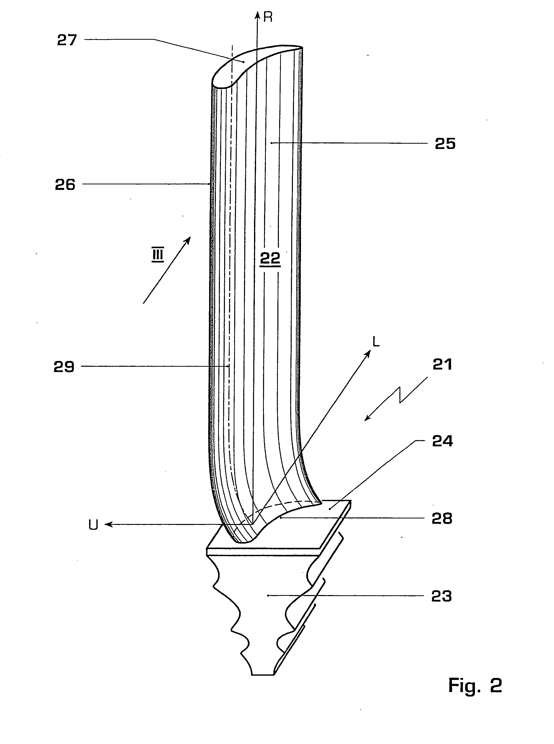
[0023]A blade airfoil, which according to a strictly geometric definition is created as a result of the parallel displacement of a
generatrix along a blade airfoil profile as a directrix, is to be understood by an untwisted blade airfoil. The
generatrix in this case can be straight or also curved, and with each translation of the
generatrix along the blade airfoil profile, however, each point of the generatrix is displaced by the same amount and in the same direction. During a movement along the directrix, the generatrix, therefore, is moved purely translationally and experiences no rotational movement. A curved generatrix in this case defines a curved but untwisted blade airfoil.
[0007]A turbomachine blade is disclosed, comprising a blade airfoil, which extends with a longitudinal extent of the blade airfoil from a blade root to a blade tip, wherein the turbomachine blade has an installed radial direction, an installed circumferential direction and also an installed axial direction, and also a stacking line, and wherein an
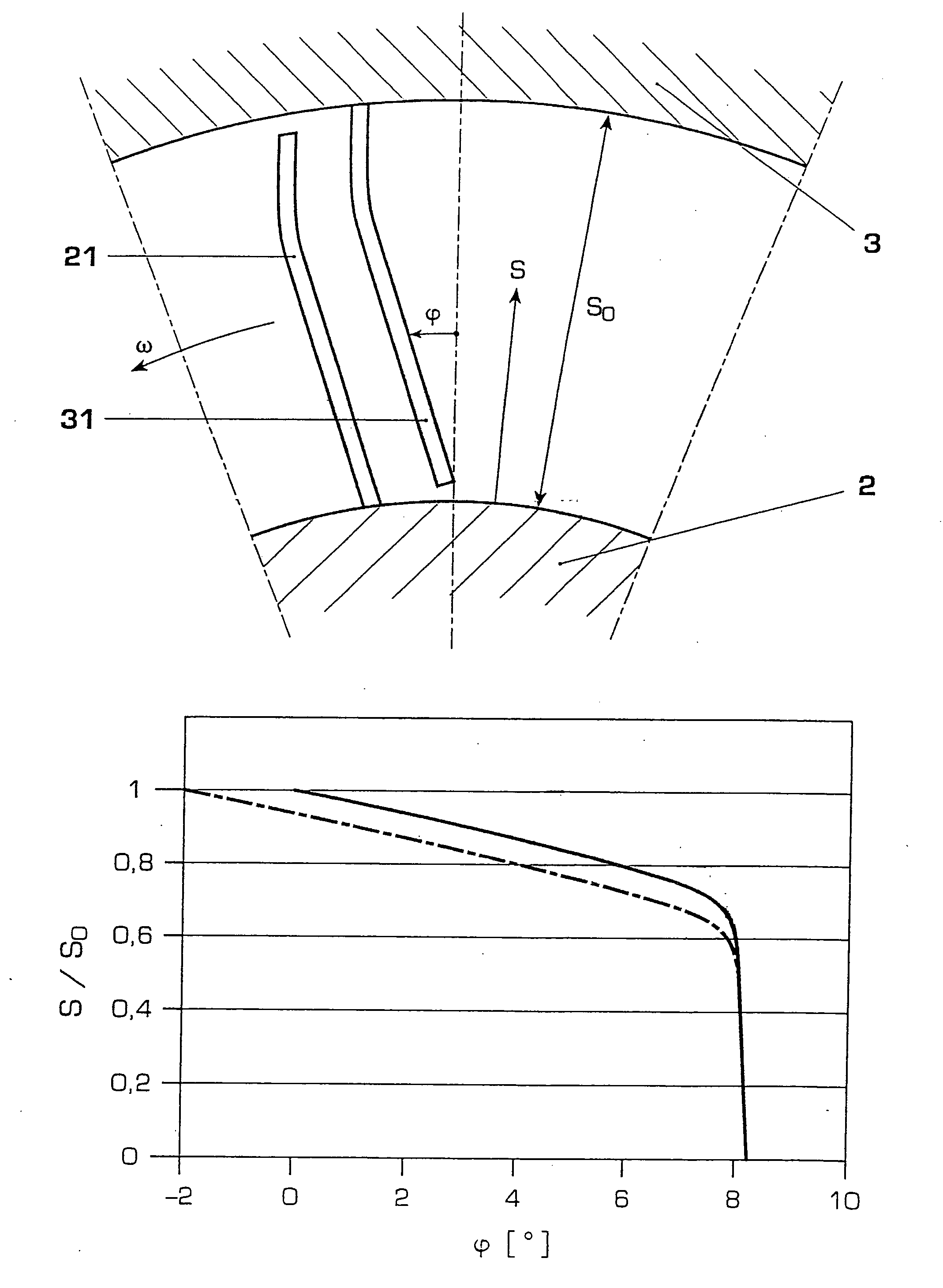
angle of inclination is defined as the angle which a projection of the stacking line has with the installed radial direction, in a plane which is spanned by the installed circumferential direction and the installed radial direction, wherein the
angle of inclination (φ) varies along the longitudinal extent of the blade airfoil.
[0025]Consequently, a turbomachine
stator blade, which comprises a blade root and a blade tip, wherein the blade root is arranged on the casing-side end of the blade airfoil and the blade tip is arranged on the hub-side end of the blade airfoil, is characterized in that the angle of inclination in the region of the blade tip, according to amount, is larger (7±3 degrees) than in the region of the blade root (0±2 degrees at the end of the region). A turbomachine rotor blade, which comprises a blade root and a blade tip, wherein the blade root is arranged on the hub-side end of the blade airfoil and the blade tip is arranged on the casing-side end of the blade airfoil, is characterized in that the angle of inclination in the region of the blade root, according to amount, is larger (7±3 degrees) than in the region of the blade tip (0±2 degrees at the end of the region). The boundary between the two regions with the appreciably different angles of inclination lies at a relative blade length of 0.7±0.1.
[0026]If the blade airfoil is arranged with an angle of inclination, then this means that the pressure face and the suction face of the blade airfoil are oriented either inwards or else outwards in the installed radial direction. In one exemplary embodiment of a turbomachine stator blade, the stacking line, that is to say the
trailing edge of the blade, is curved in such a way that in the region of the blade tip, that is on the hub-side end of the blade airfoil, the pressure face of the blade airfoil is oriented inwards in the installed radial direction, that is to say on the hub-side. The pressure face of a stator blade, therefore, is oriented in a manner pointing away from the blade platform in the region of the blade tip, at least on the
trailing edge of the blade airfoil. The blade airfoil of a stator blade in the region of the
trailing edge is convexly curved towards the pressure face, that is to say the curvature of the bend points towards the pressure face. In one development of the stator blade, the stacking line extends in the root region, that is to say on the casing-side end of the blade airfoil, at least radially, or the airfoil, by the pressure face in the region of the trailing edge, is oriented outwards in the installed radial direction, that is to say on the casing side or towards the blade platform. In one exemplary embodiment of a turbomachine rotor blade, the stacking line is curved in such a way that in the region of the blade root, that is on the hub-side end of the blade airfoil, the suction face of the blade airfoil, in the region of the greatest profile thickness, is oriented inwards in the installed radial direction, that is to say on the hub side. The suction face of a rotor blade, therefore, in the region of the blade root, is oriented towards the blade platform, at least in the region of the greatest profile thickness. The blade airfoil of a rotor blade, in the region of the greatest profile thickness, is convexly curved towards the suction face, that is to say the curvature of the bend points towards the suction face. In one development of the rotor blade, the stacking line extends in the tip region, that is to say on the casing-side end of the blade airfoil, at least radially, or the blade airfoil, by the suction face, is oriented outwards in the installed radial direction, that is to say on the casing side or in a manner pointing away from the blade platform.
[0027]A turbomachine blade of the aforementioned type of construction is suitable for example as a blade for a blade
cascade which is exposed to axial through-flow. In one exemplary embodiment, it concerns a blade for a
steam turbine, especially for a high-pressure or medium-pressure
steam turbine. The described type of construction with
turbine blades, which are used in turbines with a hub-tip ratio in the range of between 0.60 and 0.95, displays very advantageous effects.

