Liquid waste management system

Inactive Publication Date: 2008-06-26
ABBOTT LAB INC
View PDF28 Cites 38 Cited by
  • Summary
  • Abstract
  • Description
  • Claims
  • Application Information

AI Technical Summary

Benefits of technology

[0023]The liquid waste management system described herein allows for feedback control of the vacuum lev

Problems solved by technology

One drawback involves excessive space requirements and, consequently, excessive cost, relative to a system that has only one wash cup, no vacuum vessel, and no gutter system.
Such debris can result in a blockage of flow of liquid.
Furthermore, the gutter system 24 is difficult to clean.
Another drawback of the system of drains based on gravity induced flow is that the laboratory drain 42 into which the waste liquid ultimately flows has to be at a lower level than the floor (not shown) on which the automated diagnostic instrument stands.
The liquid waste management system of the ARCHITECT® i2000SR instrument does not a

Method used


Image

  • Liquid waste management system
  • Liquid waste management system
  • Liquid waste management system

Examples


Embodiment Construction

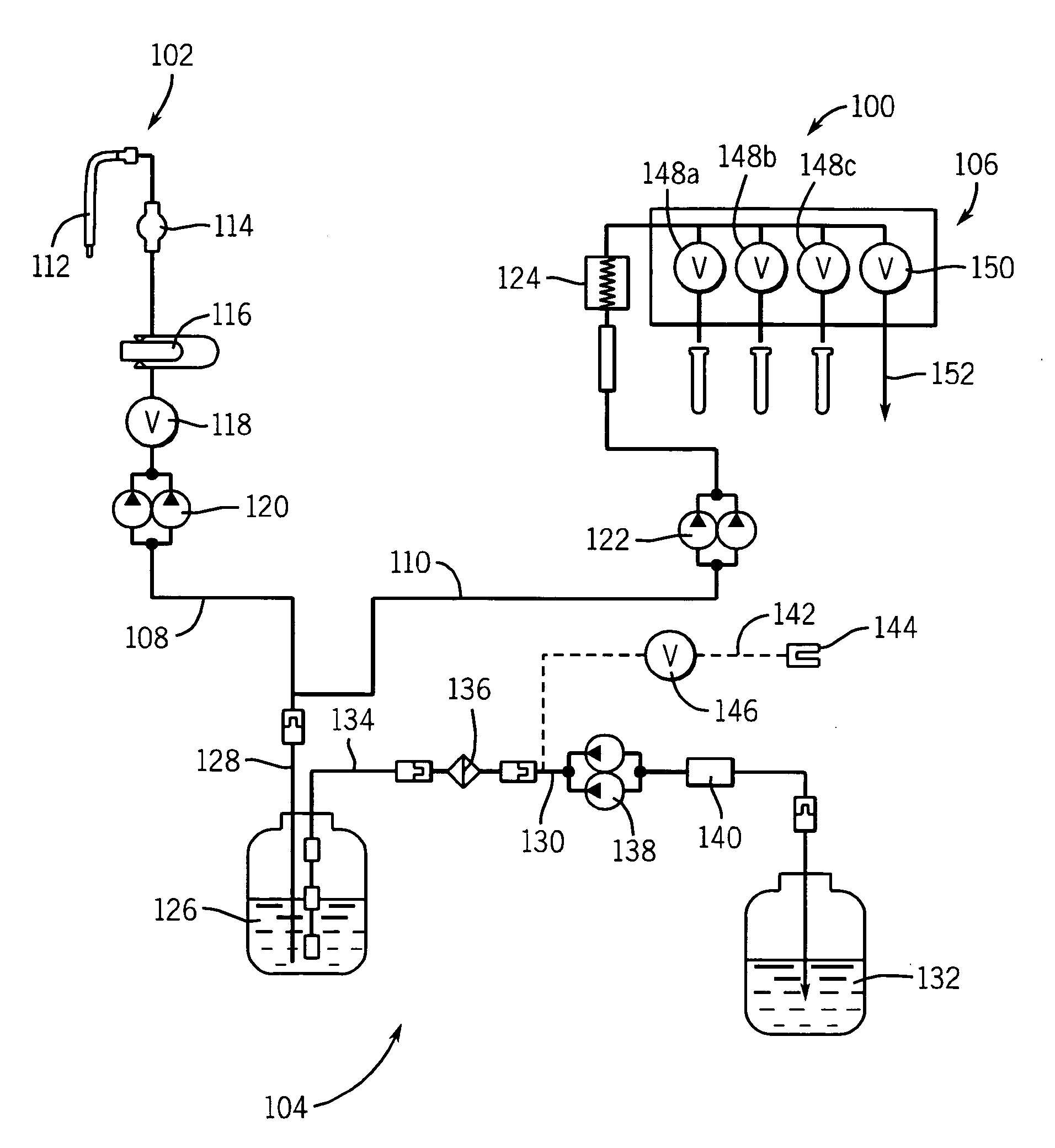
[0030]As used herein, the expression “automated diagnostic instrument” means a diagnostic instrument wherein involvement of an operator in the assay processing steps is minimal. As used herein, the expression, “on-board container” means a container that fits within the confines of the automated diagnostic instrument and is capable of moving with the instrument when the instrument is moved. As used herein, the expressions “liquid waste” and “waste liquid” are used interchangeably. As used herein, the expression “active wash cup” means a wash cup that uses a separate pump to provide a flow of buffer to the wash cup for washing the exterior surface of a pipette probe for reagents; the expression “passive wash cup” means a wash cup that does not use a separate pump to provide a flow of buffer to the wash cup for washing the exterior surface of a pipette probe. When a passive wash cup is used to clean a probe, the probe is plunged into the well of the wash cup, and the buffer used to cle...


PUM

PropertyMeasurementUnit
Lengthaaaaaaaaaa
Timeaaaaaaaaaa
Pressureaaaaaaaaaa

Abstract

A system for removing liquid waste from an automated diagnostic instrument. The system comprises
    • (a) an accumulator having at least one inlet for waste liquids and at least one outlet for waste liquids;
    • (b) a vacuum sub-system connected to the accumulator, said vacuum sub-system comprising a vacuum pump; and
    • (c) a drain portion for removing waste liquids comprising a peristaltic pump having spring-loaded rollers.
The liquid waste from the automated diagnostic instrument is moved by means of a pressure differential created by the vacuum pump and the peristaltic pump having spring-loaded rollers.

Description

BACKGROUND OF THE INVENTION[0001]1. Field of the Invention[0002]This invention relates to removal of waste liquid from an automated instrument, more particularly, an automated instrument that employs a variety of liquids.[0003]2. Discussion of the Art[0004]The ARCHITECT® family of automated diagnostic instruments requires fluid handling systems that employ at least one sub-system for aspirating and dispensing samples and reagents, at least one sub-system for dispensing buffers, at least one sub-system for dispensing pre-trigger fluids and trigger fluids, and at least one sub-system for handling liquid waste.[0005]Through the aspiration process, samples are moved from sample containers and assay reagents are moved from reagent bottles for dispensing into reaction vessels. In addition, wash buffer is dispensed for priming and flushing. Trigger solutions and pre-trigger solutions are also dispensed into reaction vessels.[0006]Pipette probes, together with syringes and valves, are used ...

Claims


Application Information

Patent Timeline
IPC IPC(8): B01D29/88G21C17/00B01L99/00
CPCB01L9/52G01N2035/0496G01N35/1004G01N35/00B01L13/00
Inventor RAJAGOPAL, GANESHWHITT, JAMES W.BERRYMAN, GEDON G.LAINS, DANIEL H.OCHRANEK, BRIAN L.BLACKWELL, GREGORY A.LUOMA, ROBERT P.RAMSEY, JACK F.
Owner ABBOTT LAB INC
Why Eureka
Try Eureka