
IP broadcasting system and a multicast group management apparatus for the same

a multicast group and broadcasting system technology, applied in television systems, two-way working systems, data switching networks, etc., can solve the problems of inefficient reporting multicast information for new additions users cannot know epg information of programs and ip information included, etc., to reduce load caused by a change in the number of ip broadcasting terminals, efficient management, and the effect of reducing the load

Inactive Publication Date: 2008-06-26
HITACHI LTD
View PDF6 Cites 44 Cited by
  • Summary
  • Abstract
  • Description
  • Claims
  • Application Information

AI Technical Summary

Benefits of technology

The present invention provides an IP broadcasting system that can efficiently manage IP broadcasting channel numbers and multicast addresses, reducing the load on broadcasters and improving service provision to users. The system includes IP broadcasting servers, IP broadcasting terminals, and a multicast group management apparatus for IP broadcasting. The IP broadcasting terminals can transmit IP broadcasting channel identifiers to the multicast group management apparatus, which holds correspondence information between the multicast group identifiers and the IP broadcasting channel identifiers. The set-top box can also be used to connect the IP broadcasting terminals to the IP multicast network. The technical effects of the invention include reducing the load on broadcasters, improving service provision to users, and shortening the time required to change channels of IP broadcasting.

Problems solved by technology

Since conventional IP broadcasting servers do not have a function to report information about TV broadcasting channels and information about multicast addresses to users, they cannot efficiently report multicast information for new addition of IP broadcasting terminals.
Therefore, by mere addition of new broadcasting programs by broadcasters, users cannot know EPG information of the programs and IP information included in it.

Method used


Image

  • IP broadcasting system and a multicast group management apparatus for the same
  • IP broadcasting system and a multicast group management apparatus for the same
  • IP broadcasting system and a multicast group management apparatus for the same

Examples


Embodiment Construction

[0040]Hereinafter, an embodiment of the present invention will be described as an example of using IPTV broadcasting as an application. However, it goes without saying that the present invention is not limited to this application. Although use of multicast addresses as multicast group identifiers is exemplified, the present invention is not limited to this.

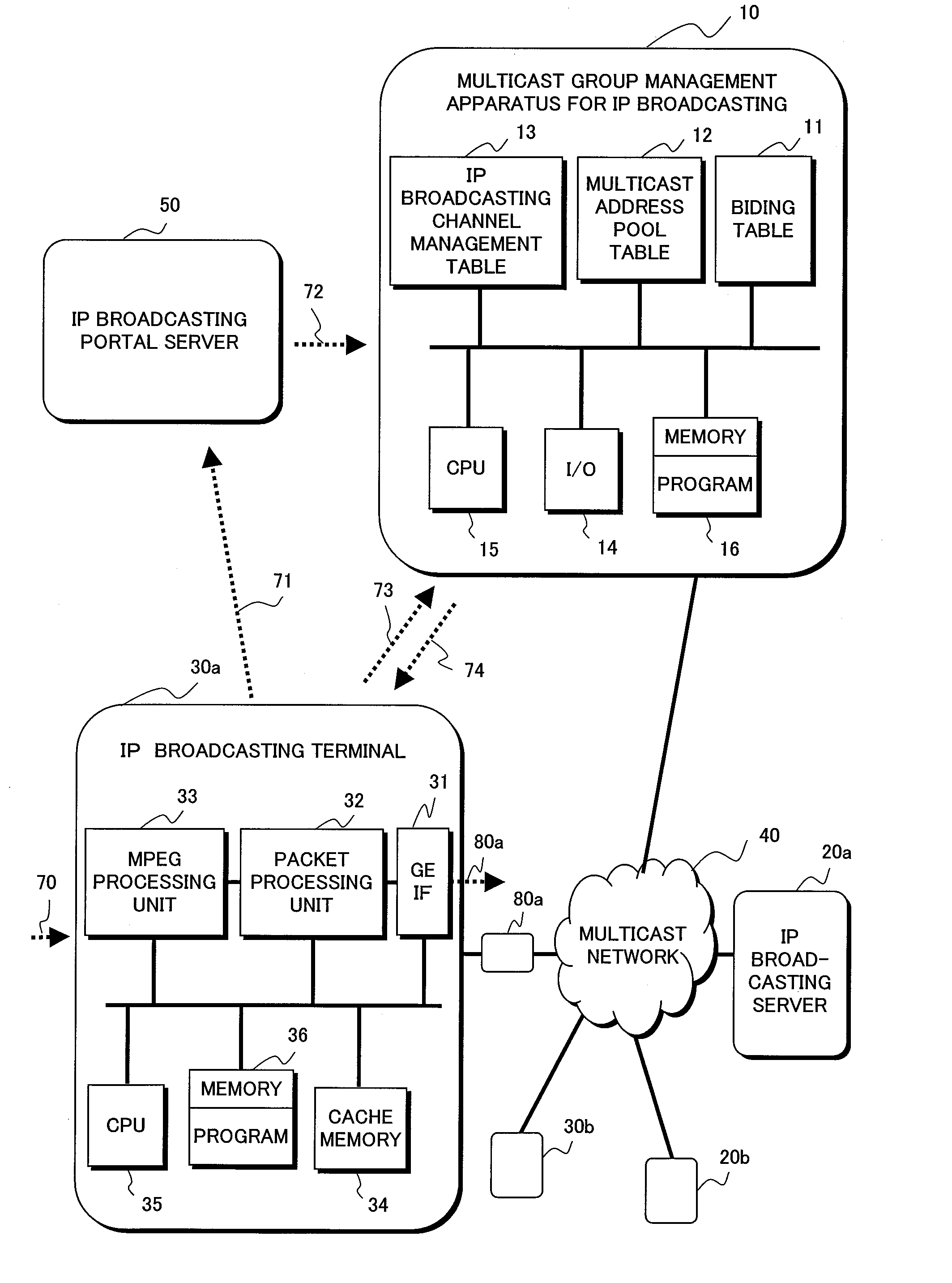
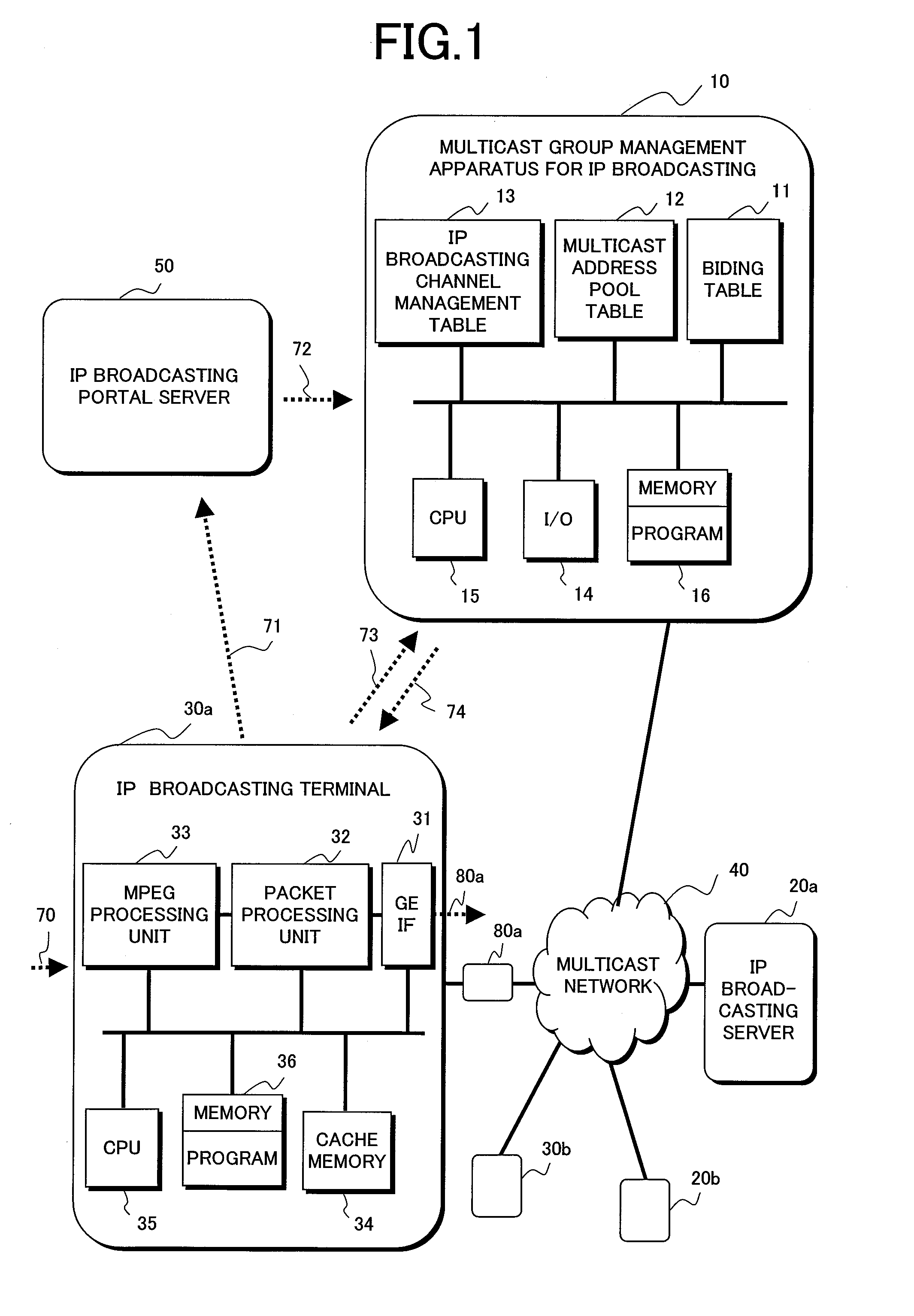
[0041]FIG. 1 is a drawing showing a first embodiment of an IP broadcasting system for providing IP broadcasting services of the present invention.

[0042]First, a network configuration is described. The IP broadcasting services are performed between an IP broadcasting server 20 and an IP broadcasting terminal 30 over a multicast network 40. The multicast network 40 includes a multicast router (not shown) that can multicast an IP packet having a multicast address as a multicast group identifier, wherein the IP packet is transmitted based on the multicast address. Two or more IP broadcasting terminals 30 may exist. A set-top box 80, w...


PUM


Abstract

The present invention provides an IP broadcasting system that can receive IP broadcasting videos over an IP multicast network. In the IP broadcasting system, a multicast group management apparatus for IP broadcasting that holds multicast group identifiers is connected via an IP multicast network over which IP broadcasting services are provided. When a user issues a request to switch an IP broadcasting channel from an IP broadcasting terminal, a query message including the requested IP broadcasting channel identifier is transmitted to a management apparatus. The IP broadcasting terminal receives a response message indicating the correspondence between the IP broadcasting channel identifier and a multicast group identifier, and transmits a video reception request message to a multicast group by using the received multicast group identifier.

Description

CLAIM OF PRIORITY[0001]The present application claims priority from Japanese application JP 2006-343320 filed on Dec. 20, 2006, the content of which is hereby incorporated by references into this application.BACKGROUND OF THE INVENTION[0002]The present invention relates to broadcasting services by use of Internet Protocol (IP), and IP broadcasting system technology for performing combined services of broadcasting and telecommunications by use of multicast technology.[0003]Multicast communication is technology for transmitting IP datagrams to members belonging to a multicast group while copying it by a multicast router, and is already developed in a wide range. So-called multicast technology complies with standard documents RFC (Request for Comments) 1112, 2236, and 3376 that are produced by IETF (Internet Engineering Task Force) and publicized by IAB (Internet Architecture Board), and is technology for managing and reporting information about members within a group that performs mul...

Claims


Application Information

Patent Timeline
Patent Type & Authority Applications(United States)
IPC IPC(8): H04N7/173H04L12/18H04L45/16H04N21/6402H04N21/6405
CPCH04L12/185H04L12/1877H04N21/4384H04L65/4076H04N21/6405H04N21/643H04N21/64322H04N21/6125H04L65/611
Inventor IKEDA, HIROKISAKAMOTO, KENICHISHINAGAWA, TAISHI
Owner HITACHI LTD
Learn More