Working Machine

a technology of working machine and rotating hub, which is applied in the direction of steering control, analogue and hybrid computing, lifting devices, etc., can solve the problems of complex and costly electrical connection between the rotatable hub and the rest of the machine, and achieve the effect of simple and cost-effective electrical connection

Inactive Publication Date: 2008-07-03
J C BAMFORD EXCAVATORS LTD
View PDF25 Cites 3 Cited by
  • Summary
  • Abstract
  • Description
  • Claims
  • Application Information

AI Technical Summary

Benefits of technology

[0005]According to the invention we provide a working machine which includes a steerable, power driven ground engaging structure and a hydraulic actuator operated working part for performing working operations, and a control apparatus which includes a mounting, a steering device for providing steering to the ground engaging structure, and a manually operable control device for controlling operation of a hydraulic control valve which in use selectively provides pressurised hydraulic fluid to the at least one actuator to operate the working part. The steering device may include a steering wheel which includes an outer rim part which is rotatable relative to the mounting, within an envelope of rotat...

Problems solved by technology

However, where the control devices are switches and the like, it is complex and costly to provide for electrical connections between the rotatable hub and the remainder of the machine.
However, operation of such ...

Method used


Image

  • Working Machine
  • Working Machine
  • Working Machine

Examples


Embodiment Construction

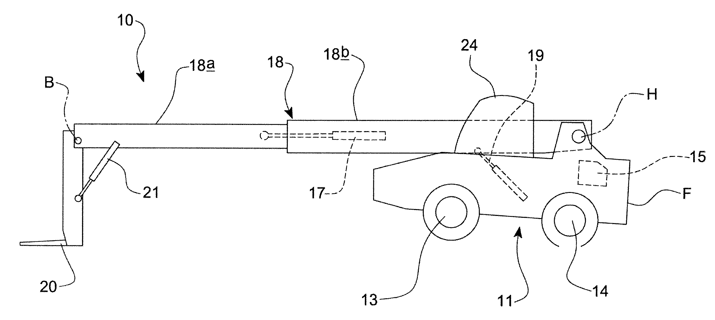
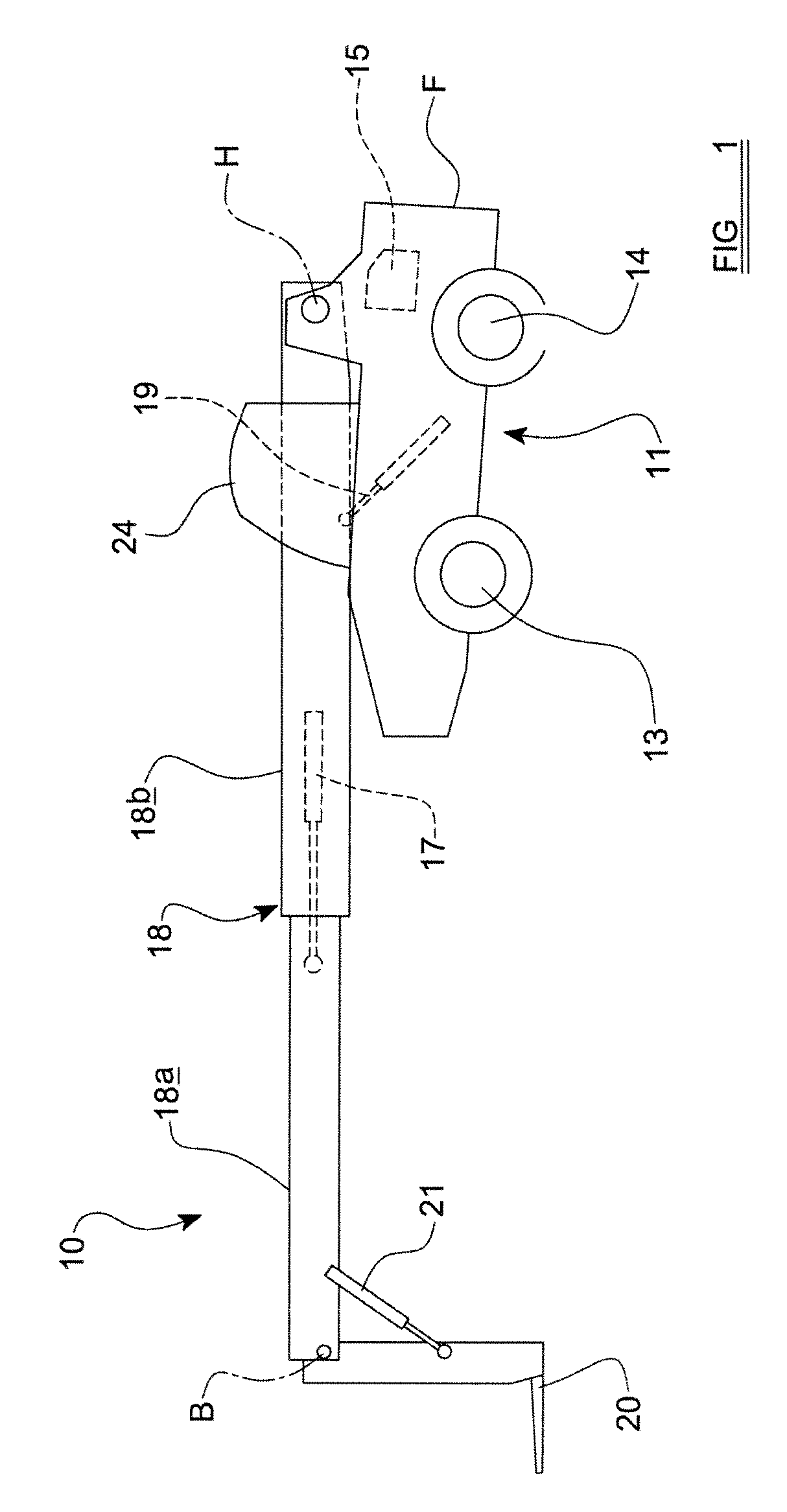
[0026]Referring to FIGS. 1 and 5 of the drawings, a machine 10 to which the present invention is applied is in this example, a loading machine having a ground engaging structure 11 provided by two pairs of ground engaging wheels 13, 14, one pair of wheels 13 in this example, being front, steerable wheels, and the other pair of wheels 14 being rear wheels (which may or may not alternatively or additionally to the front wheels be steerable), with all four wheels 13, 14 being power drivable from an engine 15 via a suitable transmission T, which may be a mechanical transmission, or of the hydrostatic kind.

[0027]The machine 10 includes a working arm which in this example is a loading arm 18 pivotally mounted to a frame F of the machine 10 for pivoting movement about a generally horizontal axis H. Such a loading arm 18 usually includes a plurality of telescopic parts or stages, e.g. two stages 18a, 18b in this example, whereby the arm 18 is linearly extendible and retractable, by means of...


PUM


Abstract

A working machine includes a steerable, power driven ground engaging structure and a hydraulic actuator operated working part for performing working operations, and a control apparatus which includes a mounting, a steering device for providing steering to the ground engaging structure, and a manually operable control device for controlling operation of a hydraulic control valve which in use selectively provides pressurised hydraulic fluid to the at least one actuator to operate the working part, the steering device including a steering wheel which includes an outer rim part which is rotatable relative to the mounting, within an envelope of rotation, about an axis, to turn a steering column which is coaxial or substantially co-axial with the axis of rotation of the steering wheel, the steering column being operatively connected to the ground engaging structure to effect steering of the machine when turned, and the control apparatus further including a hub structure which is located within or substantially within the boundary of rotation of the outer rim part of the steering wheel, and a controller, the hub structure being fixed relative to the mounting and the manually operable control device being provided by the hub structure and in use when operated, providing a signal to the controller which responds by operating the hydraulic control valve.

Description

BACKGROUND TO THE INVENTION[0001]This invention relates to a working machine having a control apparatus, the machine including a steerable, power driven ground engaging structure and a hydraulic actuator operated working part for performing working operations. Examples of machines to which the present invention may be applied are loading machines and excavating machines and tractors, which each include a transmission for driving the machine over the ground.[0002]Most typically, steering of the ground engaging structure of such a machine is performed using a steering wheel, which will be understood by those skilled in the art to include any control which includes a continuous, or a plurality of separate, circular, or near circular circumferentially extending manually graspable outer rim part or parts, which is or are connected by one or more radially extending members to a centre part where the steering wheel is operatively connected to a steering column which in use is turned to eff...

Claims


Application Information

Patent Timeline
IPC IPC(8): B60K17/356G05B11/01G06F19/00G05G13/00
CPCB66F9/20E02F9/2004Y10T74/20256B62D1/105E02F9/26B62D1/043
Inventor BROWN, CHRISTOPHER M.BROOKS, GRAHAM M.
Owner J C BAMFORD EXCAVATORS LTD
Why Eureka
Try Eureka