Plasma display panel
a technology of display panel and plasma, which is applied in the direction of gas discharge vessel/container, gas-filled discharge tube, electrode, etc., can solve the problems of insufficient light blocking function, difficult to uniformly accumulate wall charges within the discharge cell, poor contact, etc., to reduce black luminance, improve contrast, and simplify manufacturing process
- Summary
- Abstract
- Description
- Claims
- Application Information
AI Technical Summary
Benefits of technology
Problems solved by technology
Method used
Image
Examples
first embodiment
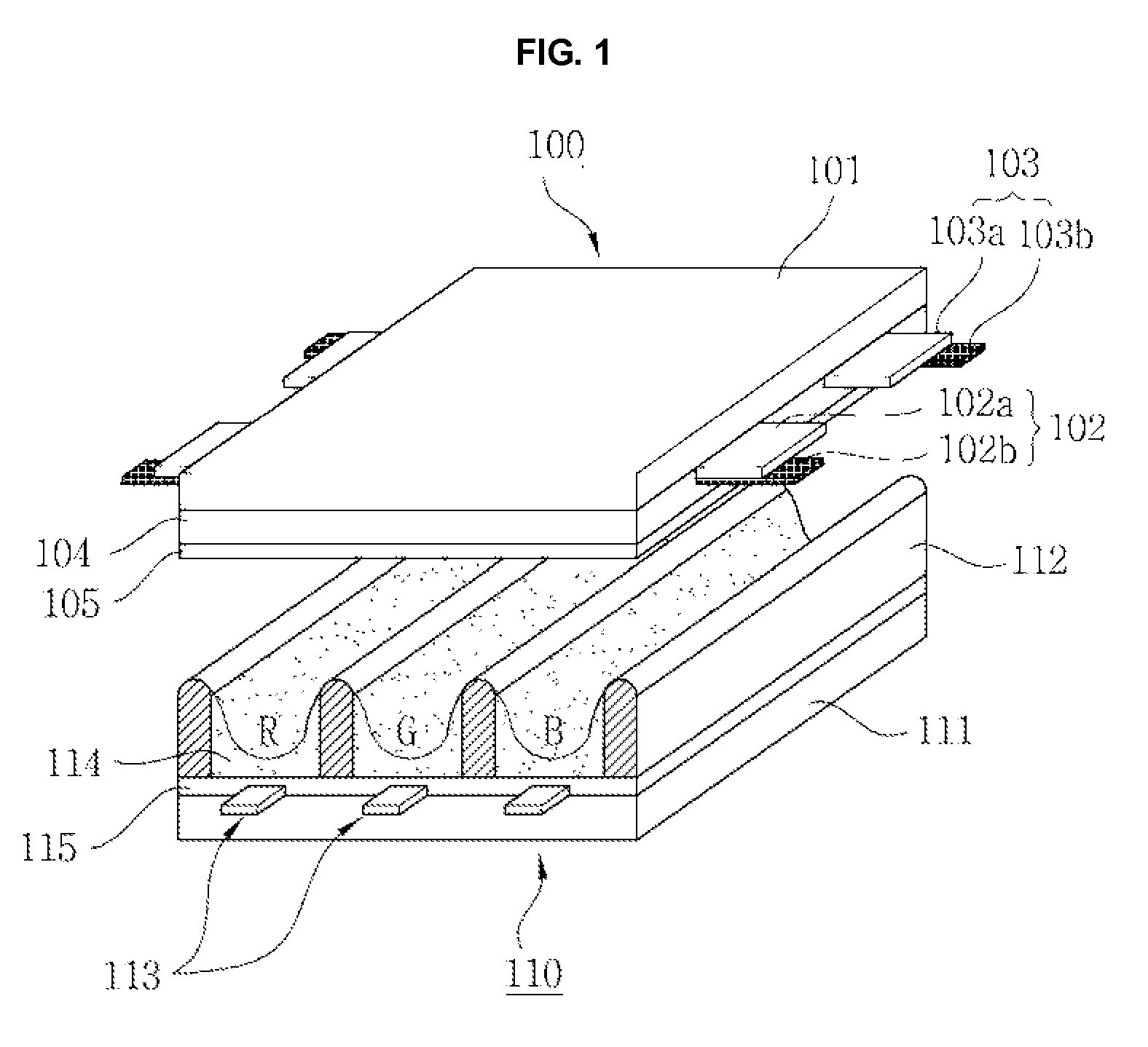
[0047]FIG. 1 shows a plasma display panel according to the present invention.
[0048] As shown in FIG. 1, the plasma display panel according to the first embodiment of the present invention comprises a front panel 100 and a rear panel 110 which are coupled in parallel to be opposed to each other at a given distance therebetween.
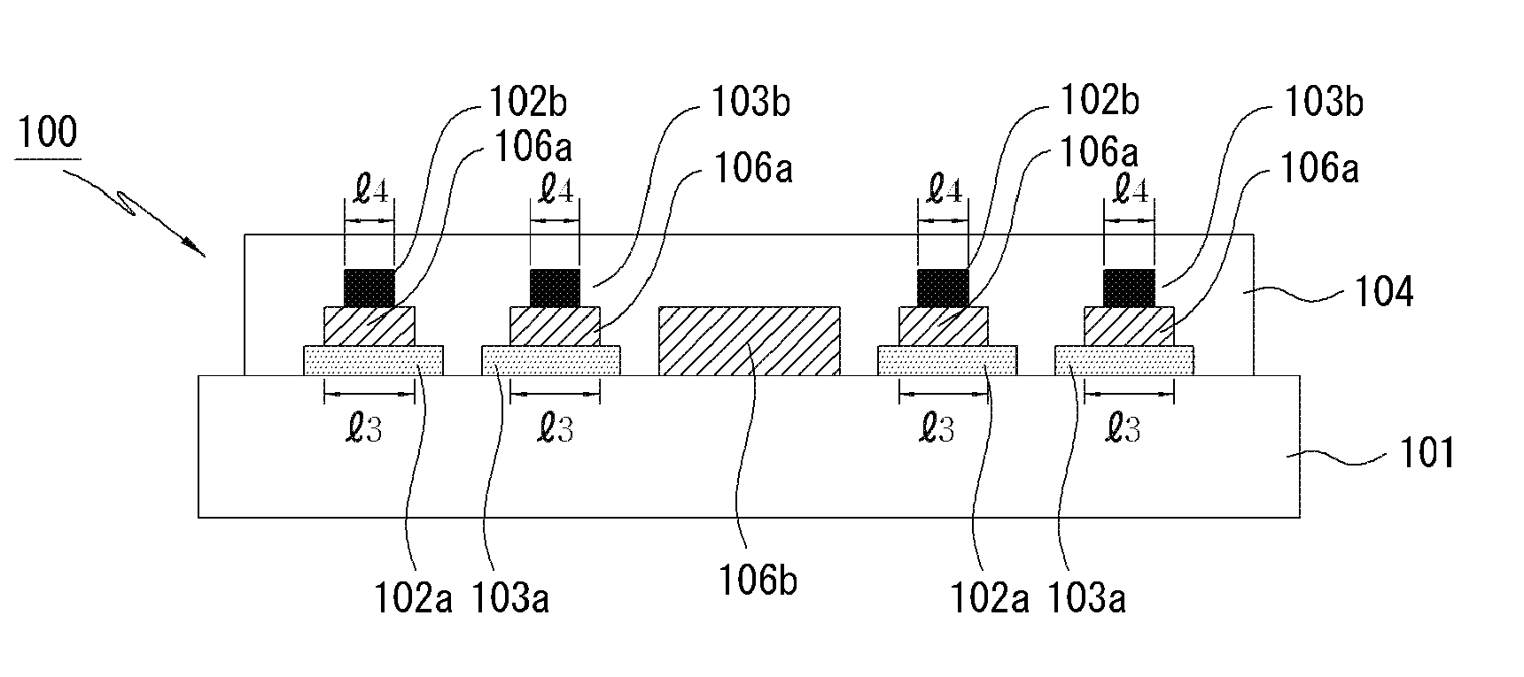
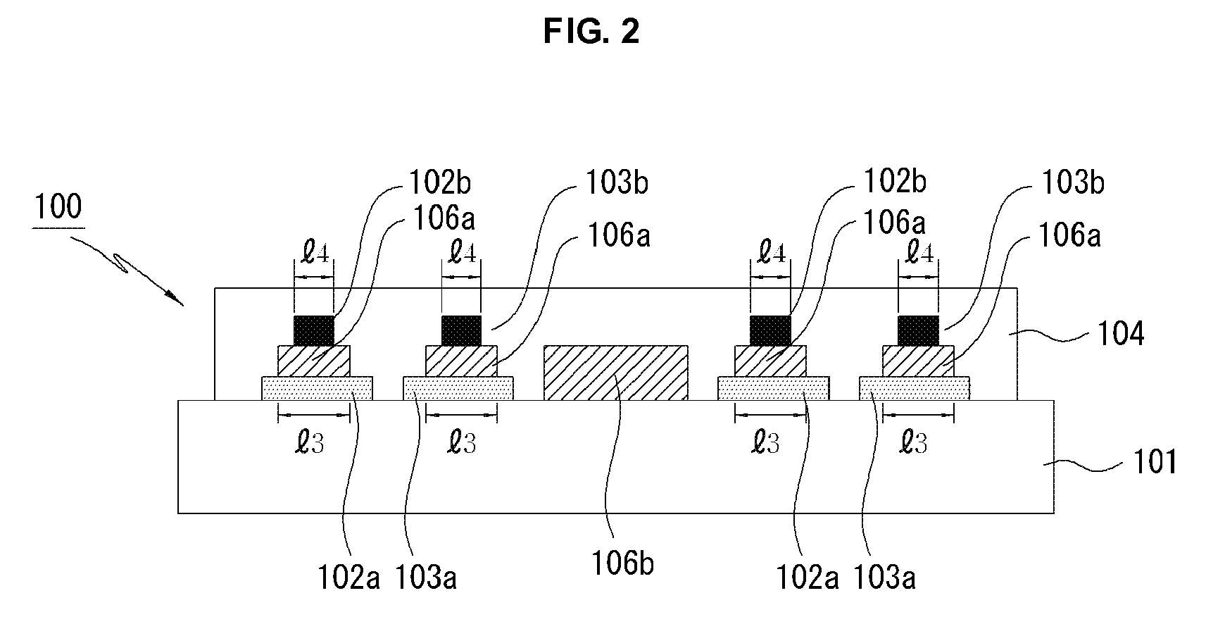
[0049] A plurality of scan electrodes 102 and a plurality of sustain electrodes 103 are formed in pairs on a front glass substrate 101 of the front panel 100 to form a plurality of maintenance electrode pairs.
[0050] The scan electrode 102 and the sustain electrode 103 each comprise transparent electrodes 102a and 103a made of transparent indium-tin-oxide (ITO) material and bus electrodes 102b and 103b made of a metal material. The scan electrode 102 and the sustain electrode 103 generate a mutual discharge therebetween in one discharge cell and maintain light-emissions of discharge cells.
[0051] The scan electrode 102 and the sustain electrode 103 are covered...
second embodiment
[0074]FIG. 4 is a schematic cross-sectional view of a front panel of a plasma display panel according to the present invention.
[0075] As shown in FIG. 4, a plurality of maintenance electrode pairs are arranged in parallel on a front glass substrate 401 of a front panel 400. The maintenance electrode pair comprise transparent electrodes 402a and 403a made of ITO material and bus electrodes 402b and 403b made of a metal material such as Ag on the transparent electrodes 402a and 403a.
[0076] Black layers 406a and 406b made of an electrically conductive material each are formed between the transparent electrodes 402a and 403a and the bus electrodes 402b and 403b.
[0077] The Black layer 406a and 406b are formed to be extended from a non-discharge region between discharge cells to a region between the transparent electrodes 402a and 403a and the bus electrodes 402b and 403b of a discharge cell adjacent to the non-discharge region. The Black layers 406a and 406b perform a light blocking fu...
third embodiment
[0094]FIG. 6 is a schematic cross-sectional view of a front panel of a plasma display panel according to the present invention.
[0095] As shown in FIG. 6, a plurality of maintenance electrode pairs comprising bus electrodes 602b and 603b made of a metal material such as Ag are arranged in parallel on a front glass substrate 601 of a front panel 600.
[0096] Since an expensive transparent electrode is not formed on the front panel 600 of the plasma display panel according to the third embodiment of the present invention unlike the front panel 100 of the plasma display panel according to the first embodiment of the present invention, the manufacturing cost of the plasma display panel decreases.
[0097] Black layers 606a and 606b made of an electrically conductive material are formed on the front glass substrate 601 of the front panel 600. The Black layers 606a and 606b perform a light blocking function for reducing reflectivity by absorbing external light generated from the outside of th...
PUM
 Abstract
Description
Claims
Application Information
 - R&D
- Intellectual Property
- Life Sciences
- Materials
- Tech Scout
- Unparalleled Data Quality
- Higher Quality Content
- 60% Fewer Hallucinations
Browse by: Latest US Patents, China's latest patents, Technical Efficacy Thesaurus, Application Domain, Technology Topic, Popular Technical Reports.
© 2025 PatSnap. All rights reserved.Legal|Privacy policy|Modern Slavery Act Transparency Statement|Sitemap|About US| Contact US: help@patsnap.com


