Electromagnetic Brake Device

a technology of electromagnetic brake and braking device, which is applied in the direction of axially engaging brakes, brake types, mechanical equipment, etc., can solve the problems of difficult to reduce the thickness (depth) of spring insertion, and achieve the effect of thinning the yoke, thinning the thickness of electromagnet, and thinning the thickness of electromagnetic brake devices

Inactive Publication Date: 2008-07-03
HARMONIC DRIVE SYST IND CO LTD
View PDF7 Cites 22 Cited by
  • Summary
  • Abstract
  • Description
  • Claims
  • Application Information

AI Technical Summary

Benefits of technology

[0023]The compression length of conical springs can thus be made adequately shorter than the compression length of cylindrically coiled springs, even when both have the same number of windings. Consequently, the spring insertion recessed part formed in the yoke used for inserting the conical spring can be made shallower. The yoke can be made thinner as a result; therefore, the electromagnet can be made thinner, and in turn the electromagnetic brake device can be made thinner.

Problems solved by technology

However, it is difficult to reduce the thickness (depth) of the spring insertion recessed part into which the compression coil spring is inserted.

Method used


Image

  • Electromagnetic Brake Device
  • Electromagnetic Brake Device
  • Electromagnetic Brake Device

Examples


Embodiment Construction

[0026]Described below is an example of a deenergization operation type electromagnetic brake device to which the present invention has been applied, with reference being made to the accompanying drawings.

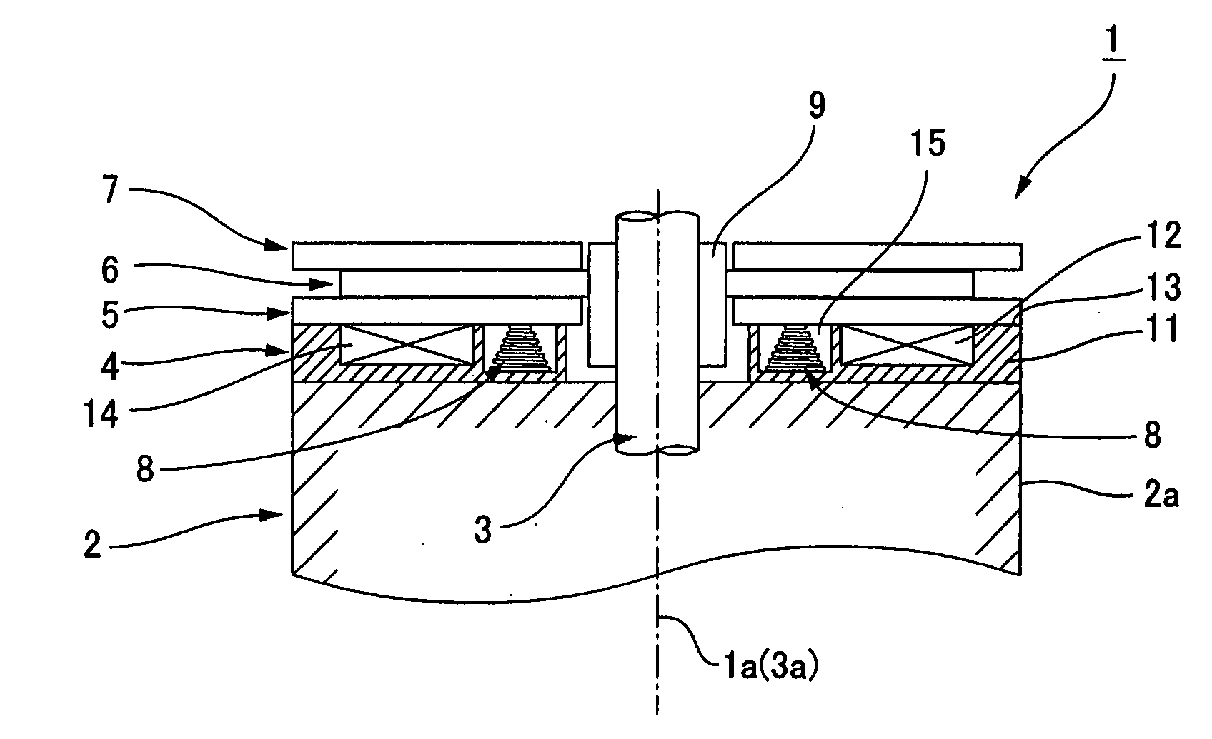
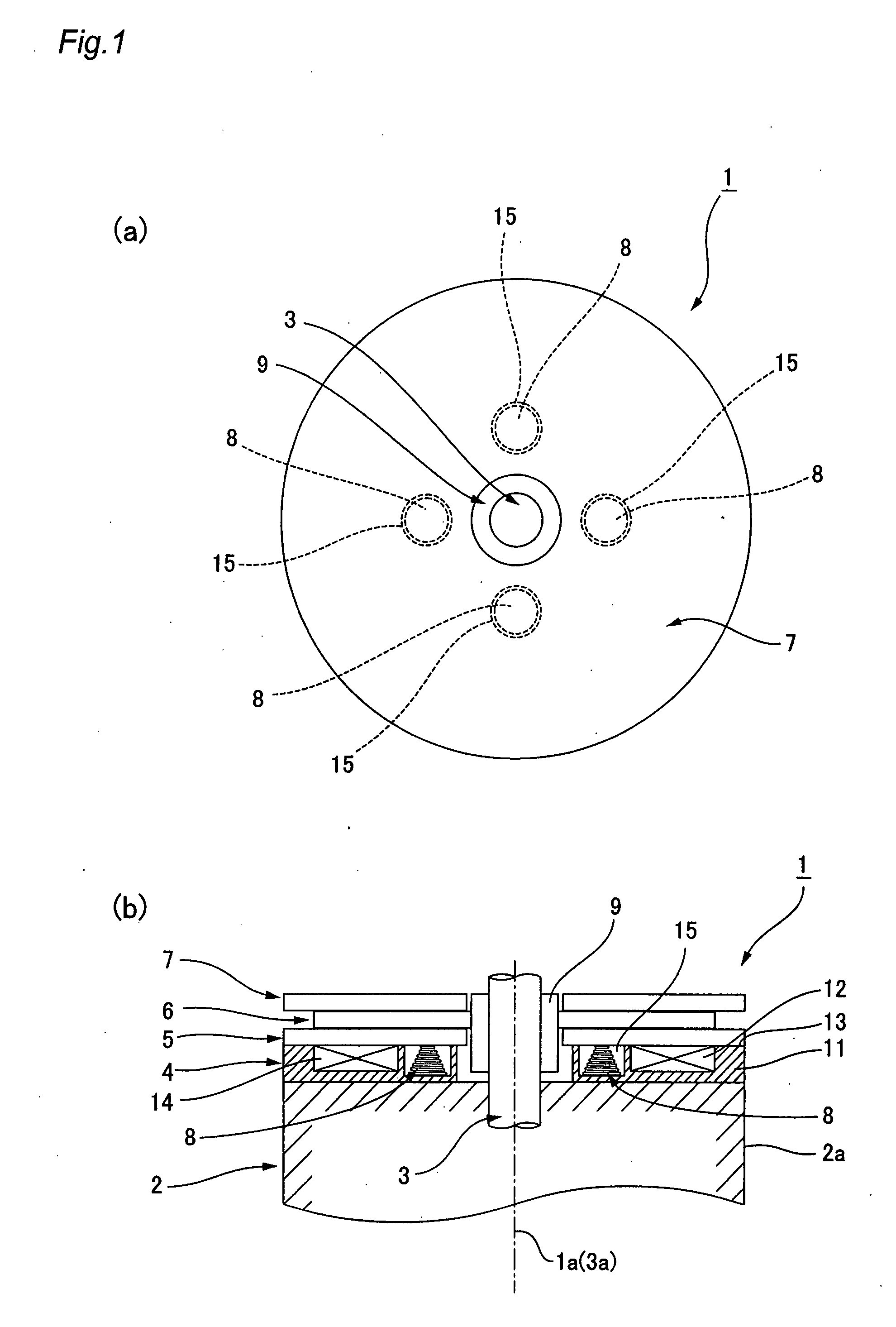
[0027]FIGS. 1(a) and (b) are a front view and vertical longitudinal cross-sectional view of the deenergization operation type electromagnetic brake device to which the present invention is applied. The deenergization operation type electromagnetic brake device 1 of this example is attached to a rotating shaft 3 of a motor 2, and is used to switch the rotation of the rotating shaft 3 to a restricted state (braked state) or a free state (unbraked state).

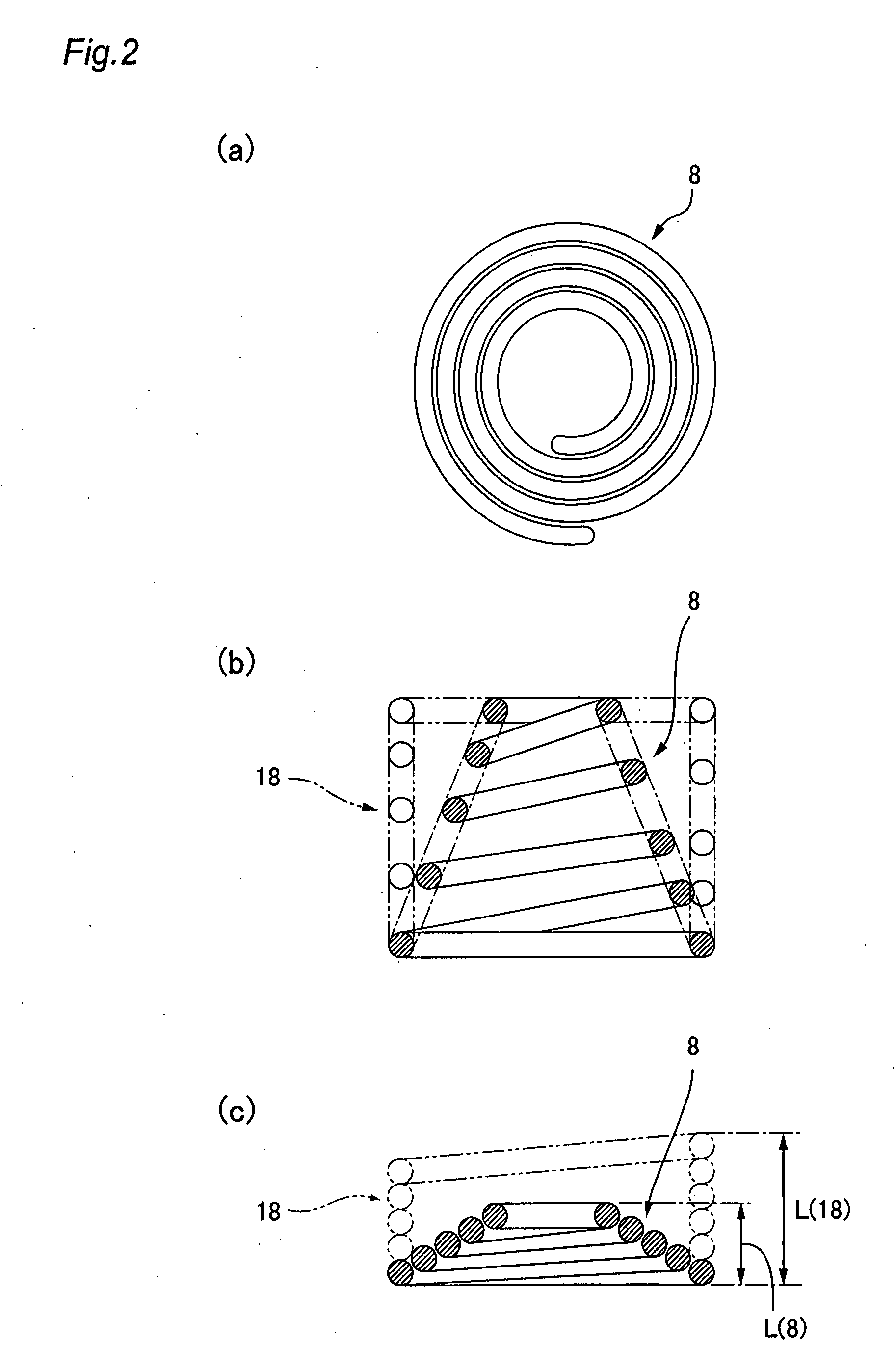
[0028]The deenergization operation type electromagnetic brake device 1 comprises an electromagnet 4 arranged in a coaxial state in the direction of an axial line 1a of the device, an armature disk 5, a friction disk 6, and a fixed disk 7. A plurality of conical springs 8 are disposed between the electromagnet 4 and the armature disk 5....


PUM


Abstract

A deenergization operation type electromagnetic brake device (1), comprising a plurality of conical springs (8) for pressing an armature disk (5) against a fixed disk (7) through a friction disk (6) held therebetween. The conical springs (8) are inserted into the spring insertion recessed parts (15) of the yoke (11) of an electromagnet (4), and held between the bottom faces of the recessed parts and the armature disk (5) in a compressed state. Since the conical springs (8) are shorter than cylindrically coiled springs in a compressed state, the spring insertion recessed parts (15) can be made shallower and the thickness of the yoke (11) determined by the recessed parts can be reduced. As a result, the electromagnetic brake device (1) can be advantageously formed flat.

Description

TECHNICAL FIELD [0001]The present invention relates to a flat deenergization operation type electromagnetic brake device that can be attached to a motor output shaft or other rotating shaft in order to restrict rotation.BACKGROUND ART [0002]Deenergization operation type electromagnetic brake devices are known as devices for imparting a braking force to a motor output shaft or other rotating shaft. The deenergization operation type magnetic device comprises a friction disk having frictional surfaces formed on either surface. A fixed disk is disposed on one side of the friction disk so as not to move in the direction of the axial line of the device, and an armature disk that is able to be attracted by an electromagnet is disposed on the opposite side of the friction disk. A compression coil spring is held between the armature disk and the electromagnet.[0003]The friction disk is attached to a rotating shaft so as to integrally rotate in a state allowing sliding in the direction of th...

Claims


Application Information

Patent Timeline
Patent Type & Authority Applications(United States)
IPC IPC(8): F16D55/224F16D65/18F16D65/22
CPCF16D59/02F16D2121/22F16D2121/14F16D65/186
Inventor KOBAYASHI, KIYOTO
Owner HARMONIC DRIVE SYST IND CO LTD
Why Eureka
Try Eureka