Torque-Limiter-Equipped Handle and Fluid Controller Having the Handle

a technology of torque limiter and fluid controller, which is applied in the direction of diaphragm valves, engine diaphragms, slip couplings, etc., can solve the problems of diaphragm valves (z) not being able to stably control fluid flow, diaphragm valves (b) being seriously damaged, and diaphragm valves (z) being unable to adjust the limit torque. , to achieve the effect of stably

Inactive Publication Date: 2008-07-03
FUJIKIN INC
View PDF7 Cites 5 Cited by
  • Summary
  • Abstract
  • Description
  • Claims
  • Application Information

AI Technical Summary

Benefits of technology

[0027]According to the invention described in claim 1 and 2, the cover portion is configured to move down and stop at the predetermined lowest position. Also, the elastic bodies are configured to push down the operating mechanism with a minimum pushing force to obtain desired effect when said cover portion reaches the predetermined lowest position. Accordingly, it is possible to provide a diaphragm with appropriate and constant compression force for obtaining the desired effect. Further, in this embodiment, the transmitted member is configured to have a serration on its surface facing the transmitting member. The serration consists of inclined surfaces and vertical surfaces that are alternately arranged along the circumferential direction. Each inclined surface of the serration is tilted upwardly along the direction in which the cover portion is rotated to move down. Therefore, when rotated in one direction, the cover portion rotates idly upon being applied excessive load. On the other hand, when rotated in the other direction, the cover portion transmits sufficient force to the handle body. Still further, it is possible to adjust the limit torque by simply modifying the angle of the inclined surfaces.
[0028]According to the invention described in claim 3 and 4, the cover portion is configured to move down and stop at the predetermined lowest position. Also, the elastic bodies are configured to provide the valve membrane with the minimum compression force to open and close the fluid channel. Accordingly, the valve membrane can open and close the fluid channel with appropriate and constant compression force so that it hardly abrades or damages during repeated use. This enables the fluid controller to stably control the flow rate over a long period. Further, in this embodiment, the transmitted member is configured to have a serration on its surface facing the transmitting member. The serration consists of inclined surfaces and vertical surfaces that are alternately arranged along the circumferential direction. Each inclined surface of the serration is tilted upwardly along the direction in which the cover portion is rotated to move down. Therefore, when rotated in the direction of closing the fluid channel, the cover portion idly rotates upon being applied excessive load. On the other hand, when rotated in the direction of opening the fluid channel, the cover portion securely transmits its force to the handle body so as to open the fluid channel. Still further, it is possible to adjust the limit torque by simply modifying the angle of the inclined surfaces.
[0029]According to the invention described in claim 5, when the cover portion is rotated in the direction of closing the fluid channel with excessive force, the inclined surfaces of the transmitting member and the inclined surfaces of the transmitted member slide along each other so that the cover portion rotates idly. This configuration allows for reducing the number of components included in the fluid controller and thereby for reducing the manufacturing cost.
[0030]According to the invention descried in claim 6 and 7, when the cover portion is rotated in the direction of closing the fluid channel with excessive force, the circular surfaces slide along the inclined surfaces so that the cover portion rotates idly. On the other hand, when the cover portion is rotated in the direction of opening the fluid channel, the spherical surfaces contacts the vertical surfaces. This enables the cover portion to transmit sufficient force to the handle body so that the fluid channel is opened.
[0031]According to the invention described in claim 8, either the transmitting pieces or the transmitted member has a spherical shape. Accordingly, when excessive force is applied to the transmitting pieces and the transmitted member, the spherical surface of either the transmitting pieces or the transmitted member idly rotates along the inclined surface of the transmitting pieces or the transmitted member. On the other hand, when the cover portion is rotated in the direction of opening the fluid channel, the spherical surfaces contacts the vertical surfaces of either the transmitting pieces or the transmitted member. This enables the cover portion to transmit sufficient force to the handle body so that the fluid channel is opened.
[0032]According to the invention described in claim 9, the fluid controller includes a reduced number of elastic bodies. Such fluid controller with reduced number of components is easy to be assembled with less manufacturing cost.

Problems solved by technology

In the conventional diaphragm valve (Z) of the configuration described above, however, diaphragm (B) tends to be damaged while it is closing the fluid channel (A-1).
This means that as the diaphragm valve (Z) is used repeatedly for a long time, the diaphragm (B) is seriously damaged.
Therefore there is a problem that such a conventional diaphragm valve (Z) cannot stably control fluid flow over a long period.
When the fluid channel (A-1) is closed in this way, the handle (E) often compresses the diaphragm too much and imposes excessive load on the diaphragm.
Accordingly, during repeated use for many years, the diaphragm (B) tends to damage and abrade.
Therefore, this valve (Z) cannot stably control fluid flow over a long period.
The valve disclosed therein, however, sometimes has a difficulty in opening the fluid channel since, in this valve, the lower end of a spherical transmitting member is engaged into a concave portion having spherical shape using pushing force of an elastic element.
This leads to a problem that it is sometimes difficult or impossible to rotate the handle in the direction of opening the fluid channel.
Also, this valve has another problem that it is difficult to slightly adjust or change the limit torque because the spring constant of the elastic element has to be modified to adjust the limit torque.
Therefore it is difficult to mass-produce this valve, and also this valve becomes very expensive.

Method used


Image

  • Torque-Limiter-Equipped Handle and Fluid Controller Having the Handle
  • Torque-Limiter-Equipped Handle and Fluid Controller Having the Handle
  • Torque-Limiter-Equipped Handle and Fluid Controller Having the Handle

Examples


first embodiment

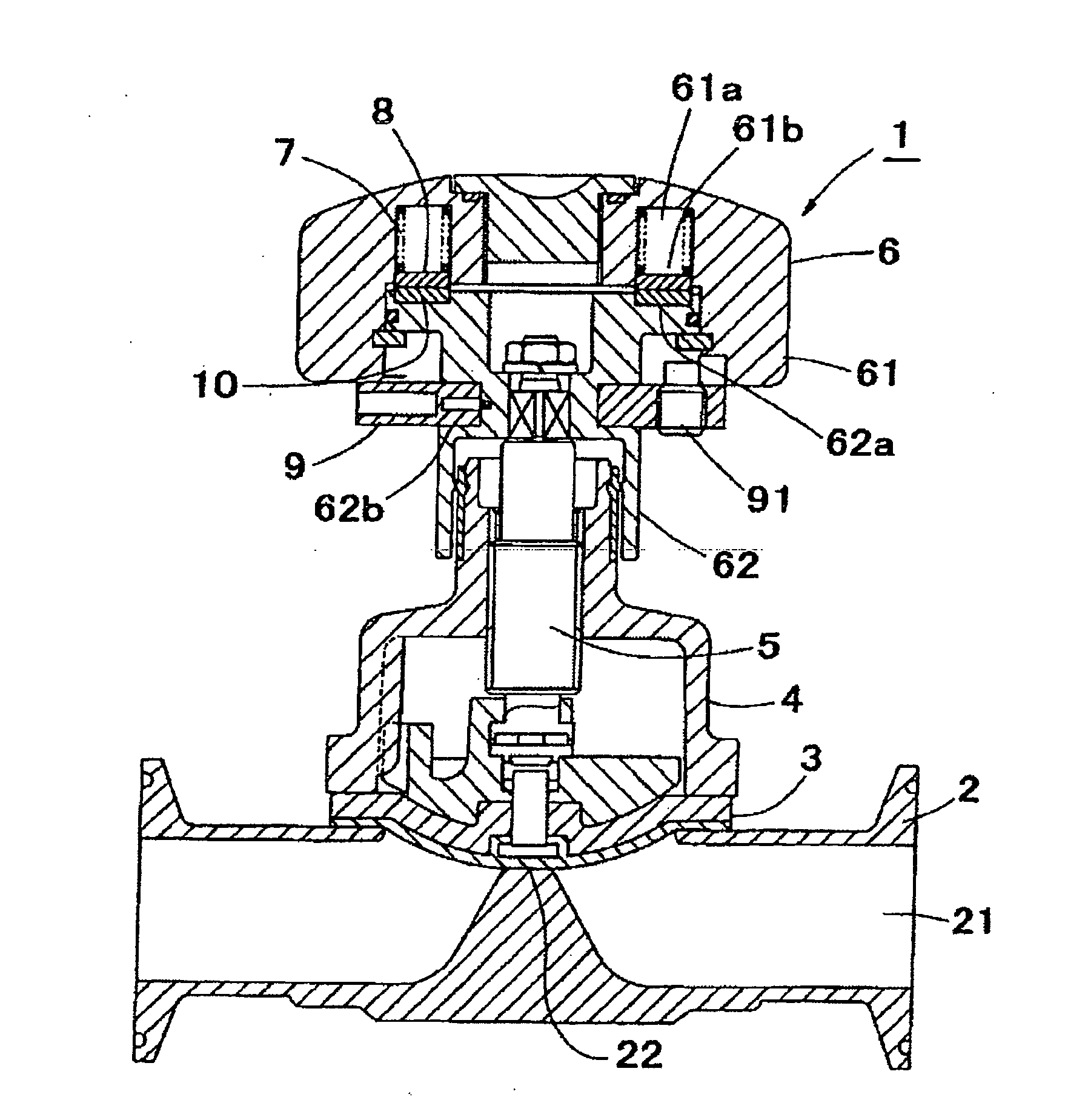
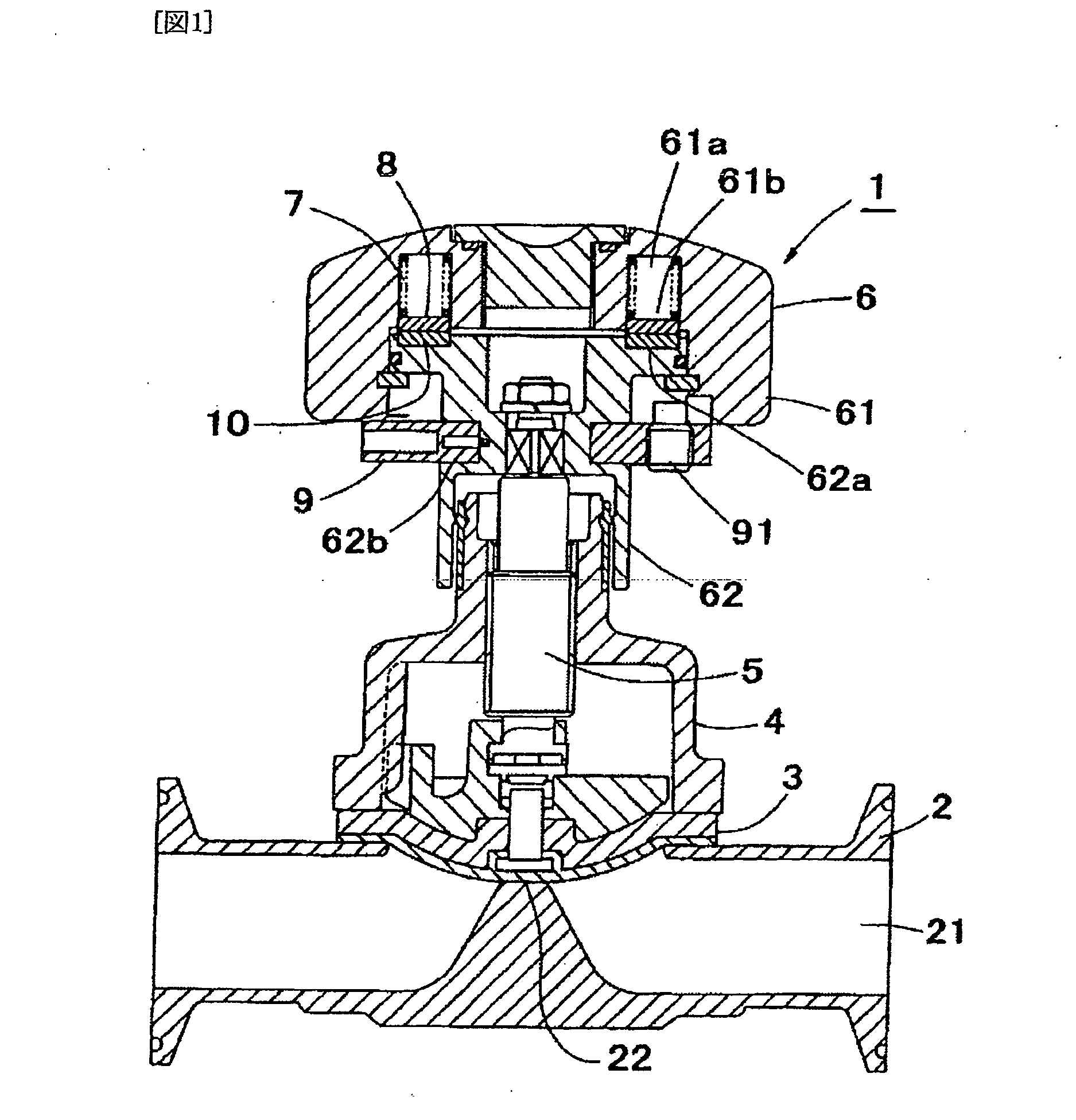
[0056]FIG. 1 is a longitudinal section that shows the fluid controller configured with a handle with a torque limiter according to the present invention.

[0057]As shown, the fluid controller (1) of the present invention comprises a valve casing (2) having a fluid channel therein, a valve membrane (3) for opening or closing the fluid channel (21), a pinching element for fixing the periphery of the valve membrane (3) between the valve casing (2) and the pinching element (4), an operating mechanism (5) having a bottom end that is connected with an upper surface of the valve membrane (3), and a handle element (6) for moving vertically the operating mechanism (5).

[0058]In the examples shown, the fluid controller of the present invention is shown as a diaphragm valve of which valve membrane (3) comprises of a diaphragm. Hence, in the description below, the valve membrane (3) is explained as a diaphragm (3).

[0059]The present invention can be applied, however, not only to a diaphragm valve b...

second embodiment

[0092]FIG. 9 is a longitudinal sectional view showing the fluid controller according to the present invention.

[0093]Since the basic configuration of the second embodiment of the fluid controller is similar to those of the first embodiment, only the difference between these embodiments will be described below. Equivalent numerals are assigned to the similar configurations and the description of these configurations will be omitted.

[0094]The difference between the fluid controllers of the first and the second embodiments is that the transmitting member (8) and the transmitted member (10) in the second embodiment are reversely positioned with respect to each other, compared to the first embodiment. In the first embodiment, the transmitting member (8) is places on the transmitted member (10), while in the second embodiment the transmitted member (10) is placed on the second embodiment. The description below will be made mainly on the configurations relating to this difference.

[0095]Insi...

third embodiment

[0107]FIG. 12 is a longitudinal sectional view of the fluid controller according to the present invention.

[0108]As the basic configuration of the third embodiment of the fluid controller is similar to those of the first embodiment, only the difference between these embodiments will be described below. Equivalent numerals are assigned to the similar configurations and the description of these configurations will be omitted.

[0109]The difference between the third embodiment and the first embodiment is that, the fluid controller according to the third embodiment comprises a plurality of spherical transmitting pieces (8). The description below will be made mainly on the configurations relating to this difference.

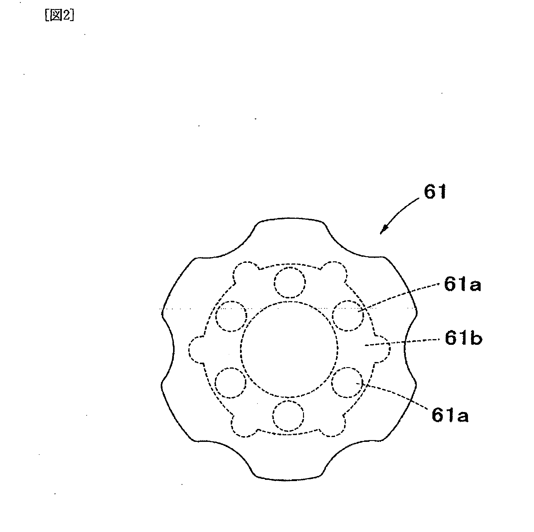
[0110]Inside the cover portion (61) of the third embodiment, a plurality of receiving holes (61a) downwardly opening is disposed. These receiving holes (61a) are aligned circumferentially with a constant spacing. Each receiving hole (61a) receives therein an elastic body (7) resp...


PUM


Abstract

To provide a handle equipped with a torque limiter capable of preventing application of excessive torque, and a fluid controller provided with the same.
An elastic body (7) has a minimum-urging force capable of developing a function desired when the handle is lowered to the lowest position. Disposed in the handle are a transmitting member (8) urged by the elastic body and a transmitted material (10) against which the lower surface of the transmitting material is pressed. The surface of the transmitted material opposed to the transmitting material or the surface of the transmitting material opposed to the transmitted material is formed with serrations along the periphery having inclined surfaces (81, 101) and vertical surfaces (82, 102) which alternately appear. The inclined surfaces of the serrations are upwardly tapered along the direction of rotation in which the cover body descends.

Description

BACKGROUND OF THE INVENTION[0001]1. Technical Field[0002]The present invention relates to a handle with a torque-limiter and a fluid controller with the handle. Particularly the present invention relates to a handle characterized in a torque-limiting function that is capable of preventing excessive torque from being applied to a diaphragm. The present invention also relates to a fluid controller with the handle to be opened and to be closed with a constant tightening force. Therefore the fluid controller will not deform valve membranes due to excessive tightening in closing operation. This results in less damage or less wearing on the valve membranes, and so the fluid controller will provide stable control on flow rate for a long period.[0003]2. Description of the Related Art[0004]Diaphragm valves are generally used to control fluid flow in a chemical industry plant for handling corrosive fluid or high purity fluid.[0005]As an example, FIG. 19 shows a diaphragm valve comprising a va...

Claims


Application Information

Patent Timeline
Patent Type & Authority Applications(United States)
IPC IPC(8): F16K31/60F16K7/16F16D7/04F16D7/08F16K7/12
CPCF16K7/126Y10T403/253F16K31/60F16K7/16F16D7/04
Inventor DAIDO, KUNIHIKOMIYAGAWA, HIDEYUKI
Owner FUJIKIN INC
Why Eureka
Try Eureka