Method and Apparatus for Three Dimensional Imaging

Inactive Publication Date: 2008-07-03
TEXAS INSTR INC
View PDF2 Cites 67 Cited by
  • Summary
  • Abstract
  • Description
  • Claims
  • Application Information

AI Technical Summary

Benefits of technology

[0013]The present invention provides significant advantages over the prior art. First, the three dimensional images produced by the present invention should be high quality with little crosstalk. Second, the lenses that separate the left and right images should be similar in size and weight to normal glasses and, therefore, comfortable to wear for extended periods. The lenses can be placed over normal prescription eyewear as well. Third, the lenses can be made using existing technology and should be relatively inexpensive with mass production. Fourth,

Problems solved by technology

First, the separation of the left and right images is crude, resulting in a sometimes poor three dimensional effect.
Second, when used in conjunction a normal display device, such as a television or computer monitor, variations in display color can result in less than perfect filtering by the lenses, such that each eye sees part of the image intended for the other.
Third, images received by the left and right eye are significantly different in color, and the viewer's brain must merge the two colors.
The stereoscopic effect from polarized lenses is quite good, but it requires specialized hardware at the source (i.e., two projectors), and therefore is not an acceptable system for television or computer gaming.
However, this requires ex

Method used


Image

  • Method and Apparatus for Three Dimensional Imaging
  • Method and Apparatus for Three Dimensional Imaging
  • Method and Apparatus for Three Dimensional Imaging

Examples


first embodiment

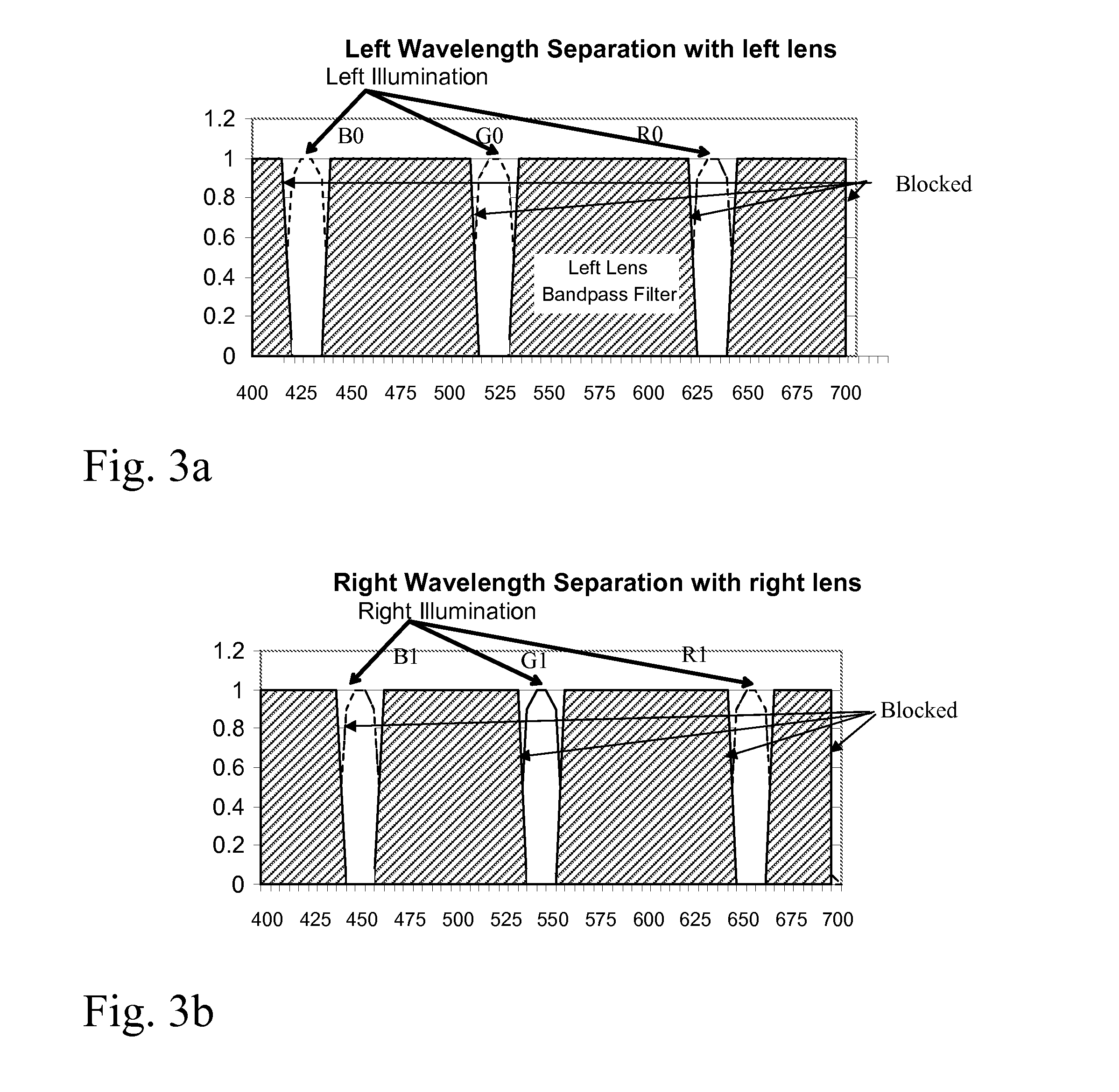
[0036]FIGS. 3a and 3b illustrate a first embodiment for selectively blocking light wavelengths in the left and right lenses 220 and 221. In FIG. 3a, the left lens 220 blocks all wavelengths other than a bandwidth of approximately 20 nm centered around R0, B0 and G0. Similarly, in FIG. 3b, the right lens 221 blocks all wavelengths other than a bandwidth of approximately 20 nm centered around R1, B1 and G1.

[0037]Optical materials which provide bandpass filters for passing multiple discrete wavelengths, while blocking others, is available, for example, from SEMROCK of Rochester, N.Y.

second embodiment

[0038]FIGS. 4a and 4b illustrate a second embodiment for selectively blocking light wavelengths in the left and right lenses 220 and 221. In this embodiment, as shown in FIG. 4a, wavelengths up to approximately 440 nm are passed by lens 220. Lens 220 also provides a bandpass filter at G0 and R0 (±approximately 10 nm), while blocking all other wavelengths above 440 nm. Similarly, in FIG. 4b, wavelengths above approximately 440 nm are passed by lens 220. Lens 220 also provides a bandpass filter at B1 and G1 (±approximately 10 nm), while blocking all other wavelength below 640 nm.

[0039]The embodiment shown in FIGS. 4a and 4b simplifies the fabrication of lenses 22, since only three wavelength ranges are filtered, rather than four ranges in FIGS. 3a and 3b. This is accomplished by passing wavelengths on the ends of the spectrum which are not used by the light sources associated with the opposite lens.

third embodiment

[0040]FIGS. 5a and 5b illustrate a third embodiment for selectively blocking light wavelengths in the left and right lenses 220 and 221. In this embodiment, only the range of wavelengths associated with the opposite lens are filtered; all other wavelengths are passed. Hence, for lens 220, only the wavelengths within a range of ±10 nm of R1, G1 and B1 are filtered out, while all other wavelengths are passed. Similarly, as shown in FIG. 5b, for lens 221, only the wavelengths within a range of ±10 nm of R0, G0 and B0 are filtered out, while all other wavelengths are passed.

[0041]This embodiment has the advantages that (1) only three wavelength ranges are filtered out, thus simplifying the fabrication of the lenses and (2) most wavelengths are passed, which will cause the least effect on the viewers perception of light apart from the display device. Thus, the viewer does not need to remove the lenses in order to see other things in the viewing room, and will not be distracted by object ...


PUM


Abstract

A display generates a three dimensional image by generating light from light sources having a first set of wavelengths to produce left eye images and generating light from light sources having a second set of wavelengths, different from the first set of wavelengths, to produce right eye images. The left eye images and right eye images are received by the viewer through a pair of lenses, where a left eye lens passes the first set of wavelengths and blocks the second set of wavelengths and the right eye lens passes the second set of wavelengths and blocks the first set of wavelengths.

Description

CROSS-REFERENCE TO RELATED APPLICATIONS[0001]Not ApplicableSTATEMENT OF FEDERALLY SPONSORED RESEARCH OR DEVELOPMENT[0002]Not ApplicableBACKGROUND OF THE INVENTION[0003]1. Technical Field[0004]This invention relates in general to imaging display systems and, more particularly, to a three dimensional imaging display.[0005]2. Description of the Related Art[0006]While three dimensional (or stereoscopic) video has been available for many decades, only recently has high quality three dimensional video been attainable. Early attempts at three dimension video used anaglyph images, where the image intended for one eye (generally the right eye) is printed through a red filter and the slightly different image intended for the other eye is printed through another color such as blue or cyan. The viewer wears glasses with a red lens on the left eye and a blue (or cyan) lens on the right eye. When viewed through the glasses, red is filtered out by the red lens, while the blue appears dark, and blu...

Claims


Application Information

Patent Timeline
IPC IPC(8): G02B27/22
CPCH04N13/0431G02B27/2207G02B30/23H04N13/334
Inventor MCCOSKY, DARREN T.
Owner TEXAS INSTR INC
Why Eureka
Try Eureka