Tilting furniture system and infinitely variable lift tensioning mechanism therefor

a technology of tensioning mechanism and tilting furniture, which is applied in the direction of wound springs, beds, sofas, etc., can solve the problems of difficult application of force for elderly people, many of the spring mechanisms in existing systems are difficult to operate over portions of the operating cycle, and certain difficulties persis

Inactive Publication Date: 2008-07-10
STONIER RUSSELL
View PDF7 Cites 9 Cited by
  • Summary
  • Abstract
  • Description
  • Claims
  • Application Information

AI Technical Summary

Benefits of technology

[0007]The invention includes, in an initial configuration, a spring tilting mechanism in which the necessity of inserting the hand or fingers of an installer into close proximity to the tilting mechanism next to the wall is eliminated during connection of a conventional bed platform to the tilting mechanism.
[0008]The invention has the further advantage that no change is necessary to the conventional configuration of the means for assembling and locking the conventional bed platform to the tilting mechanism whereby redesign of the bed platform and the support structure for the spring mechanism is avoided.
[0009]In addition, the invention has the advantage that the lift tensioning mechanism for actuating the load, such as a bed, may be infinitely variable using only a simple hand tool.

Problems solved by technology

Although the general concept has been known for some time, certain difficulties have persisted over the years.
One such difficulty is associated with the spring mechanism which is employed to raise and lower the bed, and auxiliary furniture if present.
Specifically, many of the spring mechanisms in existing systems are very difficult to operate over portions of the operating cycle, such as the first portion of movement of the bed from its open, use position (when it is parallel to the floor) as it begins its upward movement toward its associated wall.
In some cases as much as about fifty pounds of force may be required to initiate the upward tilting movement of the bed and this degree of force is difficult to apply for elderly people, or people of slight stature such as a woman who may weigh only about 110 pounds or less.
A further drawback to many existing tilting mechanisms is that installation of a bed platform to a spring mechanism requires two installers.

Method used


Image

  • Tilting furniture system and infinitely variable lift tensioning mechanism therefor
  • Tilting furniture system and infinitely variable lift tensioning mechanism therefor
  • Tilting furniture system and infinitely variable lift tensioning mechanism therefor

Examples


Embodiment Construction

[0022]Like reference numerals will be used to refer to like or similar parts from Figure to Figure in the drawings.

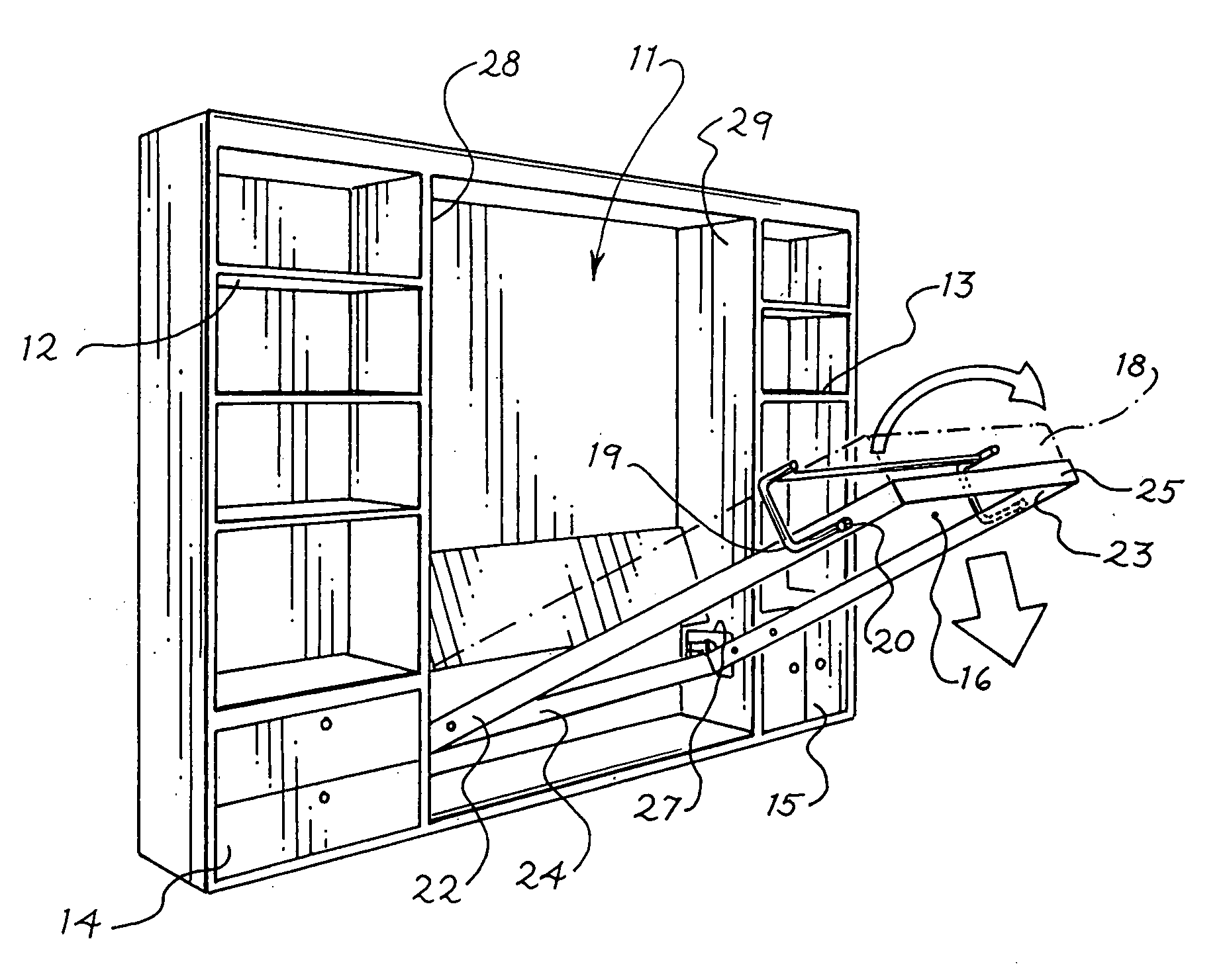
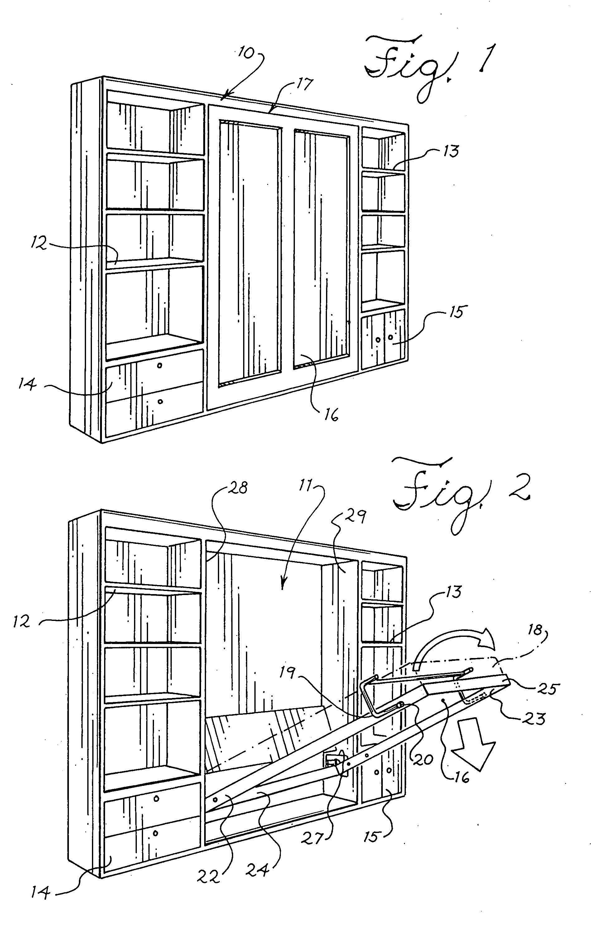
[0023]Referring first to FIG. 1, a tiltable bed assembly is indicated generally at 10 in its vertical, out of use position, the bed assembly being received within a recess 11 which is shown best in FIG. 2. In this instance a plurality of shelves are indicated at 12 and 13 and drawers or doors at 14 and 15 flanking the bed assembly 10. It will be understood that the underside 16 of the bed platform, which is indicated generally at 17, may be flush with a wall surface, or the unit may be a stand alone assemblage whose backside butts against an associated wall.

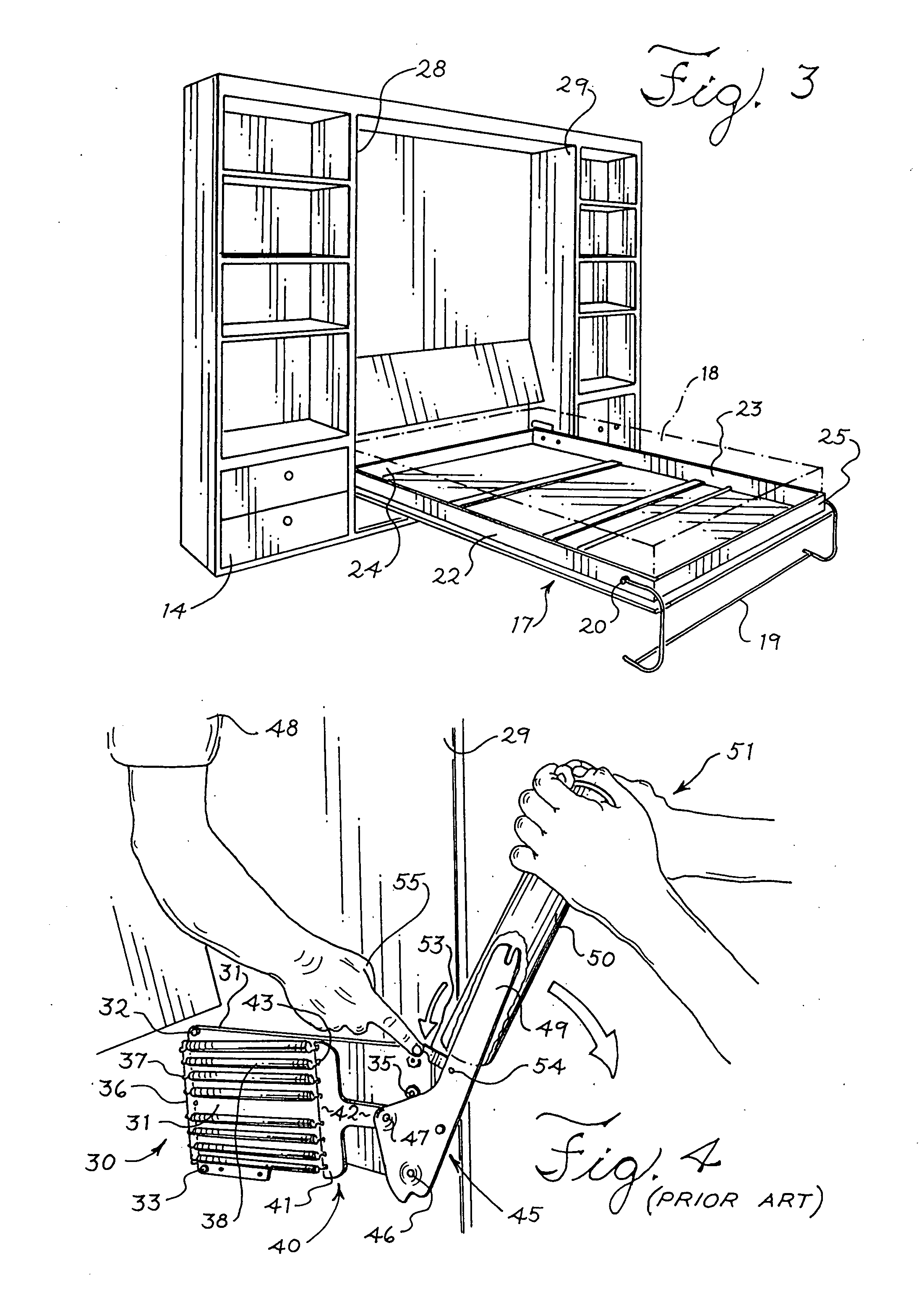
[0024]The bed assembly 10 includes, in addition to the bed platform 17, a mattress, indicated in phantom at 18 in FIGS. 2 and 3, and a support leg 19 which pivots around pivot pins 20 located near the outer extremity of side rails 22 and 23 of bed platform 17. The support leg 19 is shown in its stored, mattress restr...


PUM


Abstract

A tension mechanism for use with existing conventional bed platforms in the well known Murphy bed system in which the bed platform may be connected to the tension mechanism when the tension is at a low level by only a single installer, and the tension thereafter increased in infinite increments to any desired level by a remotely operated tool.

Description

[0001]This invention relates generally to multi-purpose furniture and specifically to a tilting furniture system and, individually or in combination therewith, an infinitely variable lift tensioning mechanism therefor. It is particularly suited for a tilting bed system of the type known for decades as a Murphy bed, but it is also adapted for use with auxiliary furniture elements, such as a desk in combination with a Murphy, or tilting, bed.BACKGROUND OF THE INVENTION[0002]There has been a trend for some years in many metropolitan areas to increase population density in both new and rehabbed buildings. In areas having building codes which permit increased density, a given floor space is more and more frequently required to serve dual purposes: daytime living and / or working space followed by nighttime sleeping space. The Murphy bed concept, which was commercially introduced over a century ago, is ideally suited to this new trend since the floor space occupied by a bed at night is avai...

Claims


Application Information

Patent Timeline
Patent Type & Authority Applications(United States)
IPC IPC(8): A47C17/40
CPCA47C17/40A47C17/46
Inventor STONIER, RUSSELL
Owner STONIER RUSSELL
Why Eureka
Try Eureka