Oil Path Structure

a technology of oil path and oil path, which is applied in the direction of gearing details, mechanical equipment, machines/engines, etc., to achieve the effect of facilitating assembly of oil amount adjusting members, reducing manufacturing costs, and simplifying the process performed on the second member

Inactive Publication Date: 2008-07-10
TOYOTA JIDOSHA KK +1
View PDF7 Cites 11 Cited by
  • Summary
  • Abstract
  • Description
  • Claims
  • Application Information

AI Technical Summary

Benefits of technology

[0006]An object of the present invention is to solve the above-described problems and to provide an oil path structure that adjusts flow rate with a simple structure while ensuring reliable sealing.
[0008]In the oil path structure formed as described above, the oil amount adjusting member is arranged together with the annular sealing member in the accommodating portion, and therefore, it becomes unnecessary to provide a portion for arranging the oil amount adjusting member separate from the accommodating portion. Further, the oil amount adjusting member is held sandwiched between the annular sealing member and a wall surface of the second member, and therefore, it is unnecessary to fix the oil amount adjusting member on the second member. Consequently, the process performed on the second member can be simplified, and the assembly of the oil amount adjusting member is facilitated. Further, the annular sealing member is provided between the joint surface of the first member and the oil amount adjusting member while being in contact with the joint surface, and therefore, sealing between the first and second oil paths can reliably be attained.
[0009]Preferably, the annular sealing member is an O-ring, and the oil amount adjusting member is a washer. In the oil path structure formed in this manner, commercially available parts can be used both for the annular sealing member and the oil amount adjusting member. Therefore, manufacturing cost can be reduced.
[0010]Further, cooling oil supplied to the electric motor is caused to flow through the first and second oil paths. By the oil path structure formed in this manner, the amount of cooling oil to be supplied to the electric motor can be adjusted to an appropriate amount in a simple structure, while reliable sealing is maintained.
[0011]As described above, according to the present invention, an oil path structure that allows flow rate adjustment with simple structure while ensuring reliable sealing can be provided.

Problems solved by technology

Further, the oil amount adjusting member is held sandwiched between the annular sealing member and a wall surface of the second member, and therefore, it is unnecessary to fix the oil amount adjusting member on the second member.

Method used


Image

  • Oil Path Structure
  • Oil Path Structure
  • Oil Path Structure

Examples


Embodiment Construction

[0017]An embodiment of the present invention will be described with reference to the figures. Throughout the drawings referred to in the following, the same or corresponding portions are denoted by the same reference numbers.

[0018]A power train shown in FIG. 1 is mounted on an FR (front engine rear wheel drive) hybrid car that has, as power sources, an internal combustion engine such as a gasoline engine or a diesel engine and a rechargeable secondary battery.

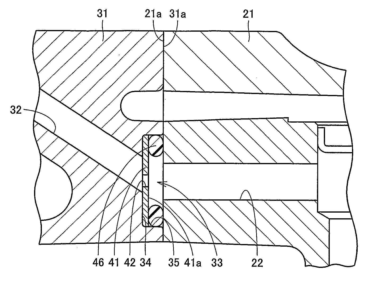
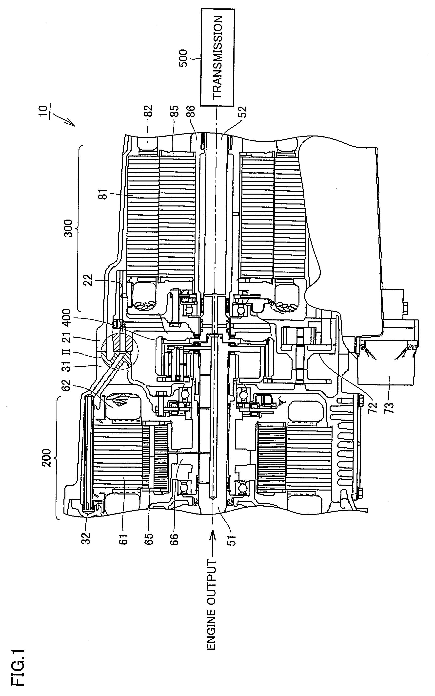
[0019]Referring to FIG. 1, a power train 10 includes a generator case 31 accommodating a motor generator 200, and a motor case 21 accommodating a motor generator 300 and assembled with generator case 31. Generator case 31 and motor case 21 have cylindrical shapes. Between motor generator 200 and motor generator 300, a power distributing mechanism 400 is arranged. On a side of motor generator 300 opposite to power distributing mechanism 400, an automatic transmission 500 is arranged.

[0020]Motor generator 200 is provided on the f...


PUM


Abstract

An oil path structure includes: a motor case having a joint surface and having a cooling oil path opened to the joint surface formed therein; a generator case having a cooling oil path formed therein and joined to the joint surface such that the cooling oil paths communicate with each other; an O-ring sealing between the cooling oil paths; and a plain washer limiting the flow rate of oil passing through the oil path. In the generator case, a recessed portion is formed at a position adjacent to the joint surface and on route of the cooling oil path. In the recessed portion, the O-ring in contact with the joint surface and the plain washer positioned on the side of O-ring opposite to the joint surface are arranged. The plain washer is sandwiched between the O-ring and a bottom surface. Thus, an oil path structure can be provided that ensures reliable sealing and allows flow rate adjustment with a simple structure.

Description

TECHNICAL FIELD[0001]The present invention generally relates to an oil path structure and, more specifically, to an oil path structure having an oil amount adjusting member for limiting amount of oil arranged on the path.BACKGROUND ART[0002]In relation to a conventional oil path structure, Japanese Patent Laying-Open No. 10-169773, for example, discloses a transmission operating device aimed at facilitating reduction in size and cost. The transmission operating device disclosed in this reference includes a cylinder housing having cylinder side flow passages formed therein, and a valve housing having valve side flow passages communicated with the cylinder side flow passages formed therein. At a mutual joint between the cylinder housing and the valve housing, an annular sealing member surrounding the outer periphery of the flow passage is arranged.[0003]Further, Japanese Patent Laying-Open No. 9-79118 discloses a motor generator of internal combustion engine aimed at suppressing tempe...

Claims


Application Information

Patent Timeline
Patent Type & Authority Applications(United States)
IPC IPC(8): F16H57/04
CPCF16H57/0424
Inventor IRAHA, YUMIADACHI, MASATOSHIMOTOIKE, KAZUTOSHIICHIYANAGI, JUN
Owner TOYOTA JIDOSHA KK
Why Eureka
Try Eureka