Wide Dynamic Range Sensor

a dynamic range and sensor technology, applied in the field of sensors, can solve the problems of image distortion, too small dynamic range of image sensors, and limited dynamic range on the upper end

Inactive Publication Date: 2008-07-10
IBM CORP
View PDF18 Cites 23 Cited by
  • Summary
  • Abstract
  • Description
  • Claims
  • Application Information

AI Technical Summary

Benefits of technology

[0007]In yet another embodiment, the present disclosure is directed to a method of increasing a dynamic range of a sensor during an integration period. The method comprises the steps of providing a sensor having a sense voltage and a means for storing charge. The sensor is responsive to energy by experiencing a decrease in the sense voltage during an integration period. The sense voltage is monitored during the integration period. If the sense voltage reaches a predetermined value during the integration period, additional charge is provided to the sensor during the integration period. At or after the end of the integration period, the sense voltage and information indicating whether the additional charge was provided to the sensor is read out.

Problems solved by technology

The dynamic range is limited on an upper end by the charge saturation level of the image sensor, and on a lower end by noise imposed limitations and / or quantization limits of the analog-to-digital converter used to produce the digital image.
Image distortion may occur when the dynamic range of the image sensor is too small to accommodate the variations in light intensities of the image scene, e.g., by having a low saturation level.
However, conventional image sensors on consumer digital cameras are limited to a dynamic range of 400:1.
These dynamic range limited image sensors result in compromised images where exposure has to be set to either the dark or bright areas of an image, resulting in either fully saturated white regions or featureless black regions.
However, these techniques and devices fall substantially short of the human eye's capabilities.

Method used


Image

  • Wide Dynamic Range Sensor
  • Wide Dynamic Range Sensor
  • Wide Dynamic Range Sensor

Examples


Embodiment Construction

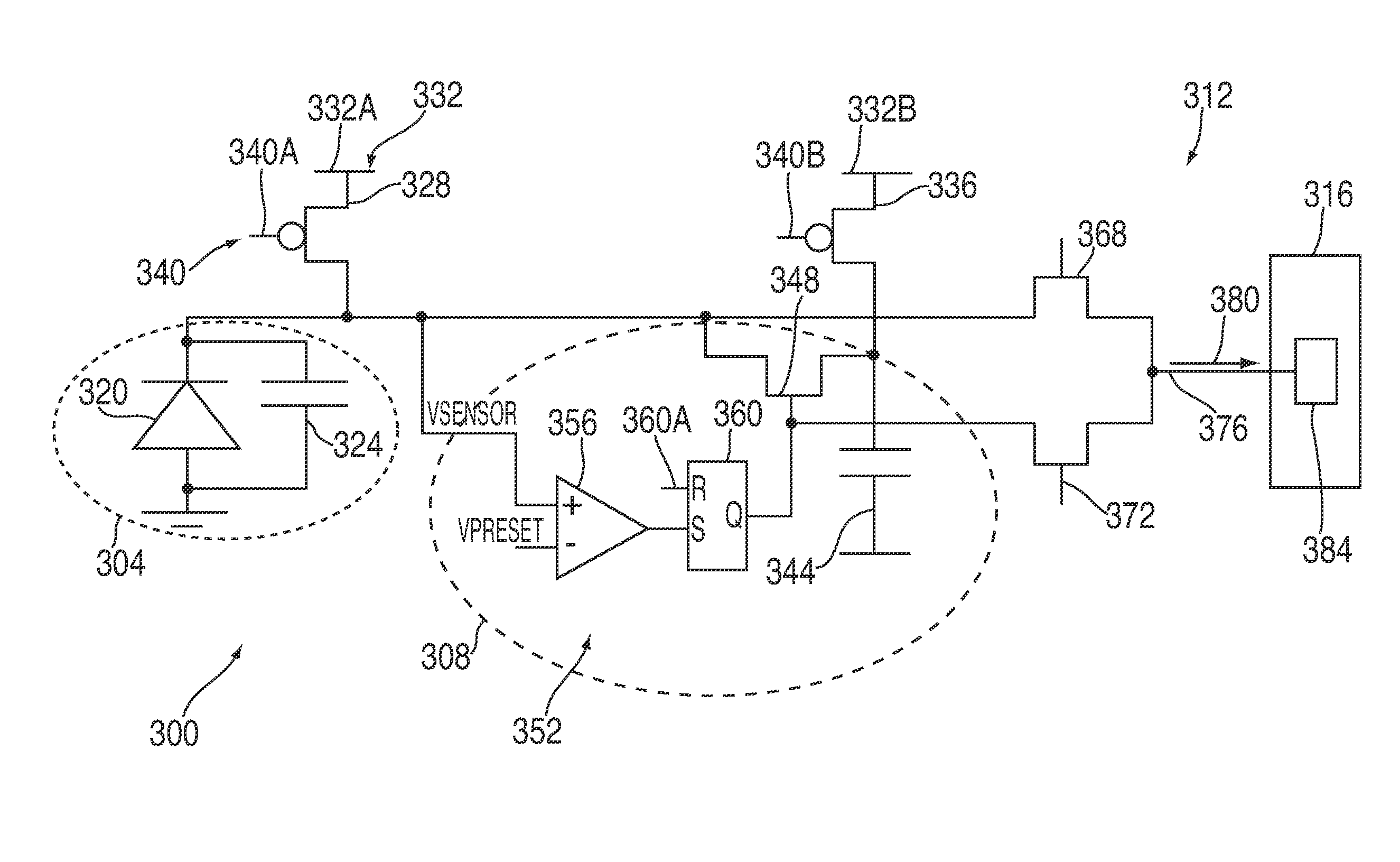
[0014]At a high level, the present disclosure is directed to methods and systems for widening and / or increasing a dynamic range of a sensor by connecting at least one switchable charge storing element to the sensor. The at least one switchable charge storing element provides an additional charge to the sensor for extending or increasing a charge collection capability of the sensor during an integration period when the sensor is exposed to levels of sensor input that would otherwise saturate the sensor. Illustrative embodiments of the methods and systems relating to this broad concept are described below.

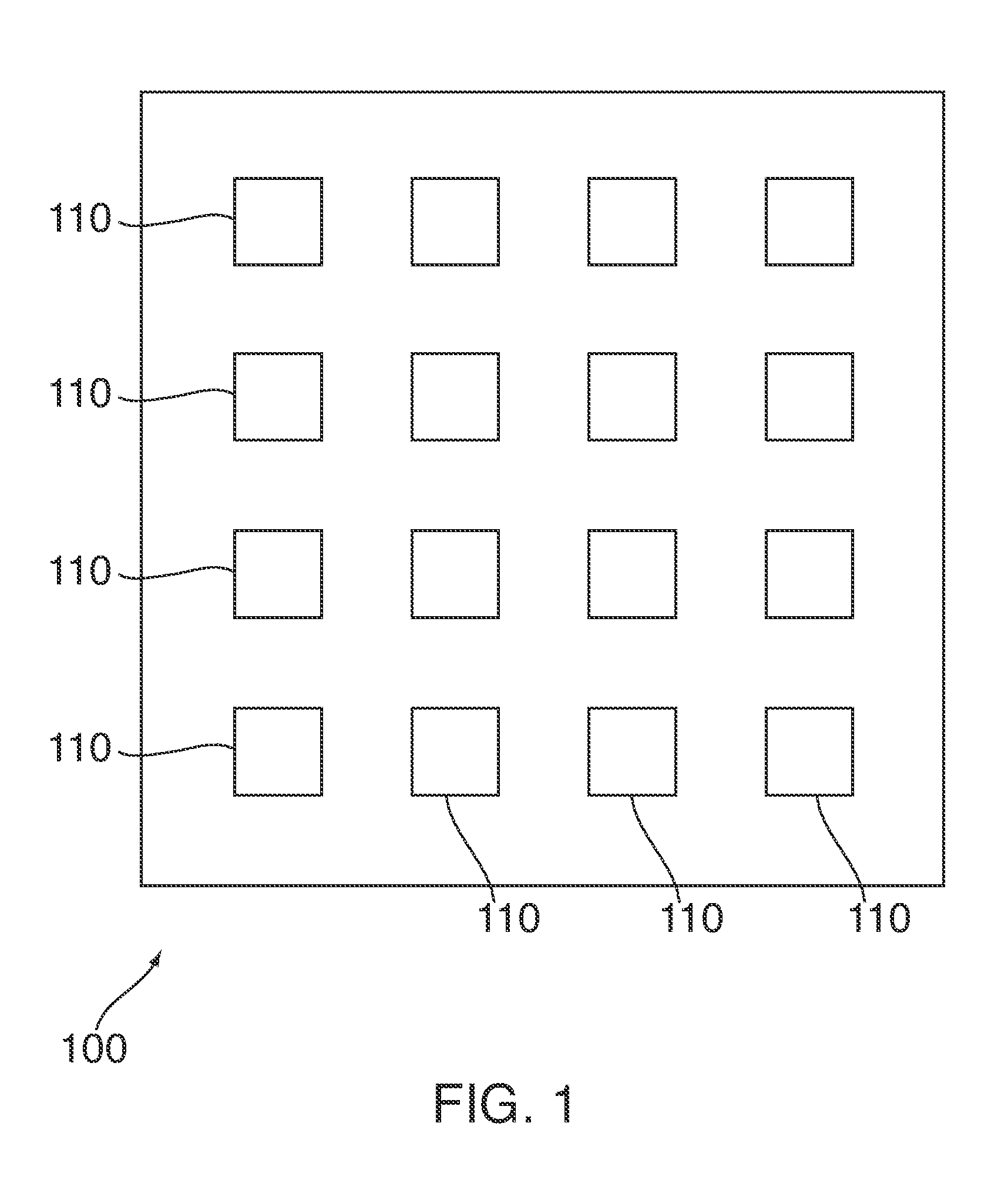
[0015]Referring now to illustrative embodiments, FIG. 1 illustrates an integrated circuit (IC) 100 that may be integrated into, but not limited to, an image capturing and / or processing device such as, but not limited to, a visible light camera, camcorder, and infrared camera. IC 100 may include, among other things, a plurality of sensor circuitries 110 arranged in an array for captur...


PUM


Abstract

A sensor and method for widening a dynamic range of sensor circuitry for sensing energy, such as light energy. The sensor circuitry includes a sensor and recharge circuitry for sharing additional charge with the sensor as needed during an integration period. Readout circuitry is provided to read out, after the integration period, the sense voltage remaining across the sensor and recharge information indicating whether the recharge circuitry shared charge with the sensor during the integration period. The sense voltage and recharge information read out of the sensor circuitry is used in a function to determine the total amount of energy sensed by the sensor during the integration period.

Description

FIELD OF THE INVENTION[0001]The present invention generally relates to the field of sensors. In particular, the present invention is directed to a wide dynamic range sensor.BACKGROUND OF THE INVENTION[0002]Various types of electronic-based sensors are used in a wide variety of applications. In many of these applications, it is desirable that the corresponding sensors have a wide dynamic range so that the sensors are able to achieve the desired results. For example, the human eye is capable of detecting light levels over a 1,000,000,000:1 absolute range, from fully adapted dark vision to fully adapted full sunlight / snow vision. At typical daylight lighting levels, the human eye can discern light contrast levels in a scene around 30,000:1. This allows the human eye to see both bright and dim objects together in a scene, as are normally present in the world around us.[0003]Image sensors are often characterized as having a certain dynamic range. The dynamic range of an image sensor is c...

Claims


Application Information

Patent Timeline
Patent Type & Authority Applications(United States)
IPC IPC(8): H01L27/146
CPCH04N3/155H04N5/37452H04N5/3559H04N25/59H04N25/772H04N25/771
Inventor HALL, EZRA D.PERRI, ANTHONY J.
Owner IBM CORP
Why Eureka
Try Eureka