
Micromechanical component having integrated passive electronic components and method for its production

a technology of electronic components and micromechanical components, which is applied in the manufacture of microstructural devices, electrical apparatus, and semiconductor devices. it can solve the problems of inconvenient use of buffer capacitors, inability to manufacture monolithically integrated sensors, and inability to integrate micromechanical components in circuit engineering. it is difficult to achieve the integration of buffer capacitors into the asic's used, and achieves considerable technical difficulties

Inactive Publication Date: 2008-07-10
ROBERT BOSCH GMBH
View PDF4 Cites 2 Cited by
  • Summary
  • Abstract
  • Description
  • Claims
  • Application Information

AI Technical Summary

Benefits of technology

[0007]An object of the present invention is to provide a possibility of further lowering the expenditure in the application of micromechanical sensors compared to the related art, and to reduce the installation space required, so as to develop new installation locations, if necessary.
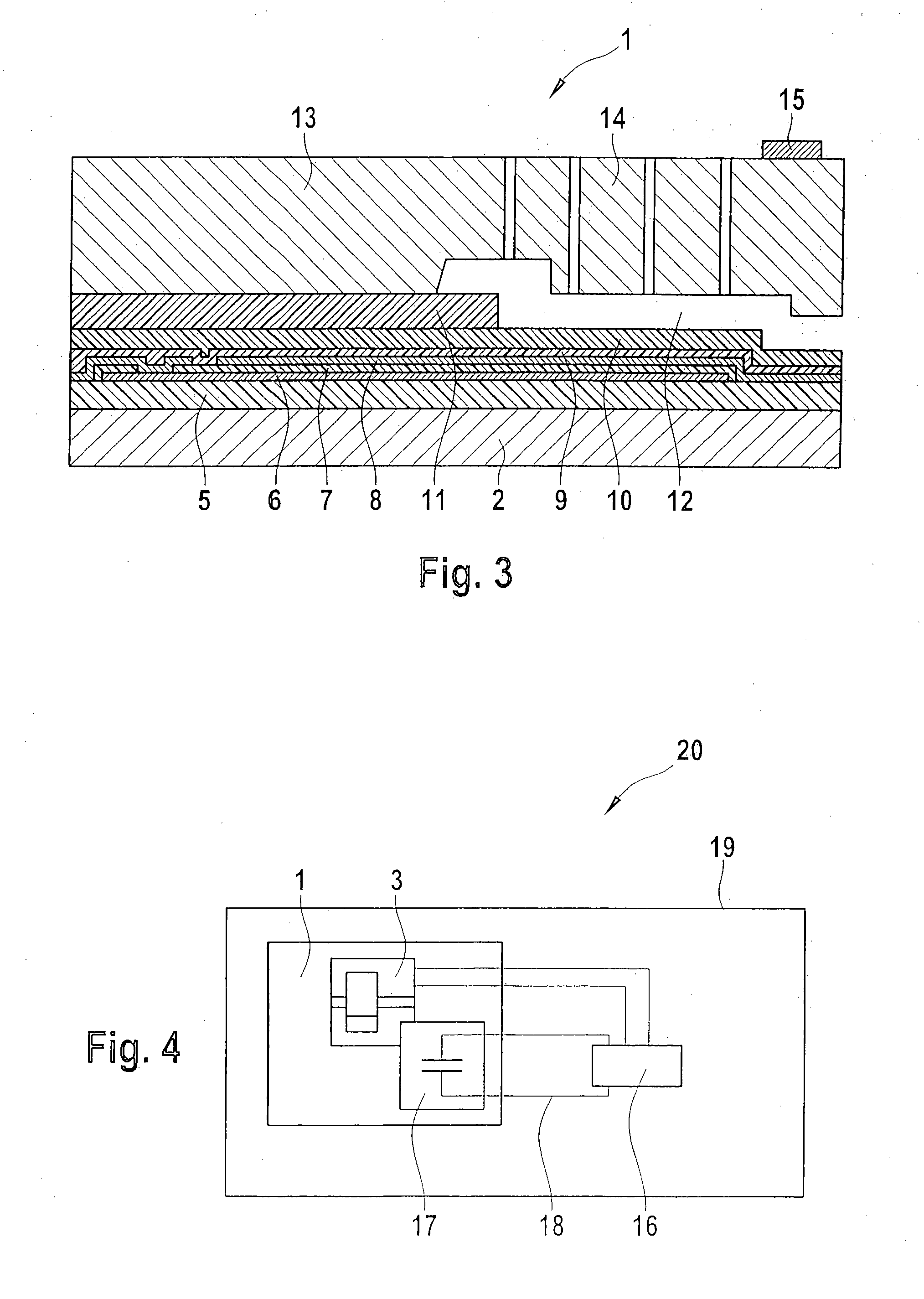
[0012]However, one should advantageously take care, in this context, that surface areas of the substrate, over which layer stacks are located, which are used as passive electronic components, and surface areas over which printed-circuit traces run for contacting micromechanically effective patternings, lie next to one another in the wafer plane, since, in that way, interfering interactions may be avoided in a simple manner by keeping appropriate minimum separation distances.

Problems solved by technology

It is known that one may manufacture monolithically integrated sensors.
Although the preparation of the micromechanical component as an integrated component in the form of so-called MEMS stacks (microelectromechanical systems) has in connection with it, in part, a considerable reduction in application expenditure when compared to discrete construction, but when it comes to assembly to a functionally complete unit, as a rule, there remains the need for a costly circuit engineering embedding of the micromechanical component.
A direct integration of buffer capacitors into the ASIC's used is connected with considerable technical difficulties, based on extremely different dimensions and interactions that are to be expected of large charge transfers during reloading of the capacitors in the immediate vicinity of microelectronic structures

Method used


Image

  • Micromechanical component having integrated passive electronic components and method for its production
  • Micromechanical component having integrated passive electronic components and method for its production
  • Micromechanical component having integrated passive electronic components and method for its production

Examples


Embodiment Construction

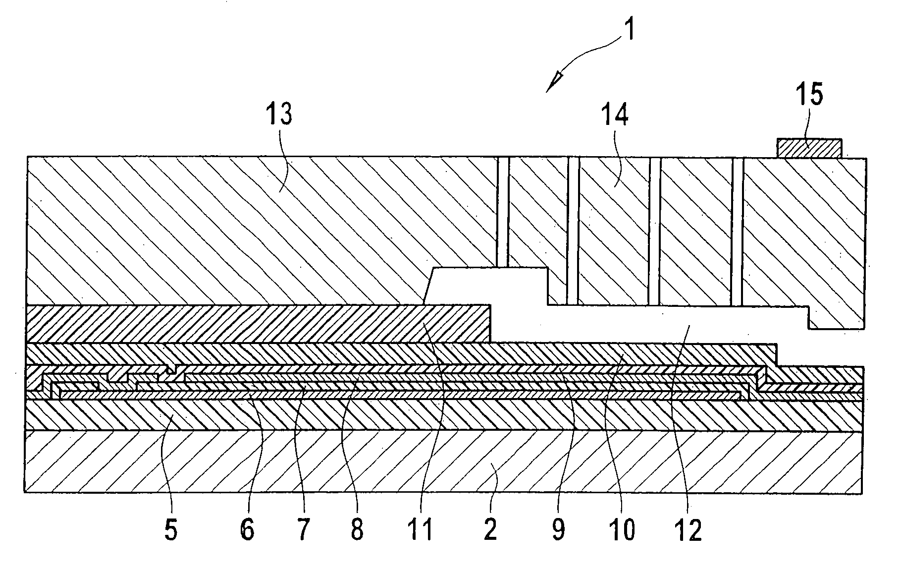
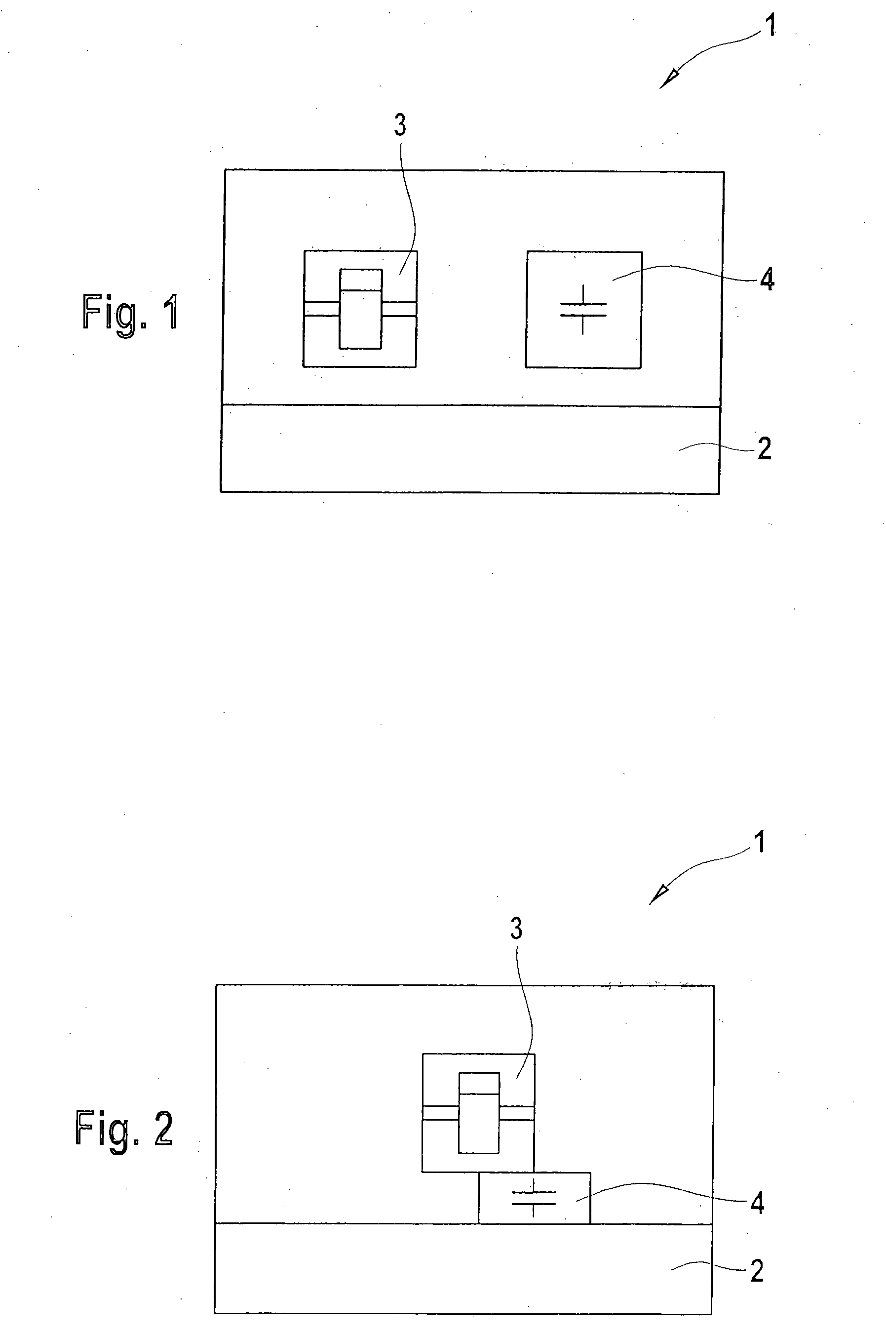
[0017]FIG. 1 shows the construction in principle of a micromechanical component 1 according to the present invention. On a common substrate 2 made of monocrystalline silicon, it has at least one functional area 3 which includes at least one micromechanical functional element. On the same substrate 2, according to the present invention, there is an additional functional area 4, which includes a structure, applied by microprocessing technology, that is able to act as at least one macroelectronic, passive component. Functional areas 3, 4, within the meaning of the present invention, are processed layer sequences, in this context, having definable functionality, if necessary, while assigning individual layers to several functional regions.

[0018]FIG. 2 shows the construction in principle of a micromechanical component 1 according to the present invention, having an underlayed passive component. Functional regions 3, 4, introduced in FIG. 1, in this case lie at least partially in differen...


PUM


Abstract

A micromechanical component includes a substrate, on which at least one layer sequence is situated, which includes at least one micromechanical functional element, and on which at least one layer sequence is situated that is able to act as at least one macroelectronic, passive component.

Description

FIELD OF THE INVENTION[0001]The present invention relates to a micromechanical component having integrated passive electronic components and a method for producing it. Micromechanical components are often used in miniaturized sensors, in security systems of motor vehicles, for example.BACKGROUND INFORMATION[0002]It is known that one may manufacture monolithically integrated sensors. In this context, using various processing steps of microprocess technology as successions of depositing steps and patterning steps, self-supporting mechanical structures are generated having specifically deflectable functional layers, which are mostly incorporated in the form of chips as sensitive components into more complex devices. Although the preparation of the micromechanical component as an integrated component in the form of so-called MEMS stacks (microelectromechanical systems) has in connection with it, in part, a considerable reduction in application expenditure when compared to discrete const...

Claims


Application Information

Patent Timeline
Patent Type & Authority Applications(United States)
IPC IPC(8): H01L29/92H01L21/02H10N99/00
CPCB81C1/00246
Inventor STAHL, HEIKOOHL, CHRISTIANFISCHER, FRANK
Owner ROBERT BOSCH GMBH
Learn More