
Microwave Sensor

a micro-wave sensor and sensor technology, applied in the field of micro-wave sensors, can solve problems such as problems in the monitoring area of targets, and achieve the effect of increasing size and increasing cos

Inactive Publication Date: 2008-07-10
OPTEX CO LTD
View PDF10 Cites 51 Cited by
  • Summary
  • Abstract
  • Description
  • Claims
  • Application Information

AI Technical Summary

Benefits of technology

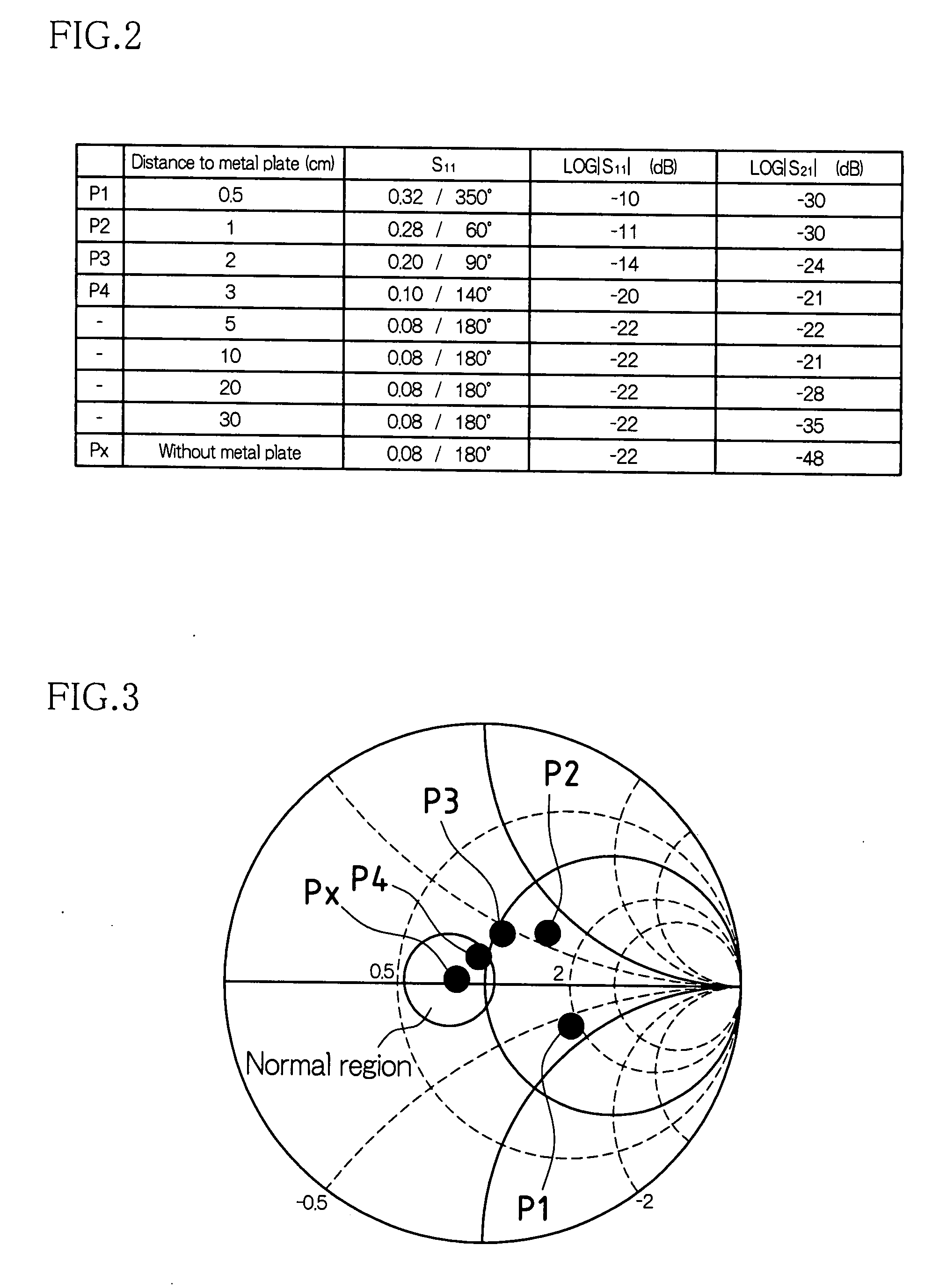
[0016]According to the microwave sensor of the present invention, with an increase in the values of the scattering parameter S11 and the scattering parameter S21, it is possible to determine that a metal plate or the like is approaching the transmission antenna unit or the reception antenna unit. Thereby, it is possible to detect masking using a metal plate or the like and set off an alarm. Because there is no need to add a passive infrared sensor or the like, it is possible to avoid, as much as possible, an increase in size as a whole, a cost increase and the like.

Problems solved by technology

In this case, the radiation of electromagnetic fields of the microwaves emitted from the antenna unit is hampered, causing problems in monitoring of targets in the detection area.

Method used


Image

  • Microwave Sensor
  • Microwave Sensor
  • Microwave Sensor

Examples


Embodiment Construction

[0042]Hereinafter, an embodiment of the present invention will be described with reference to the drawings.

[0043]1 and Detection Operation of Human Body or the Like>

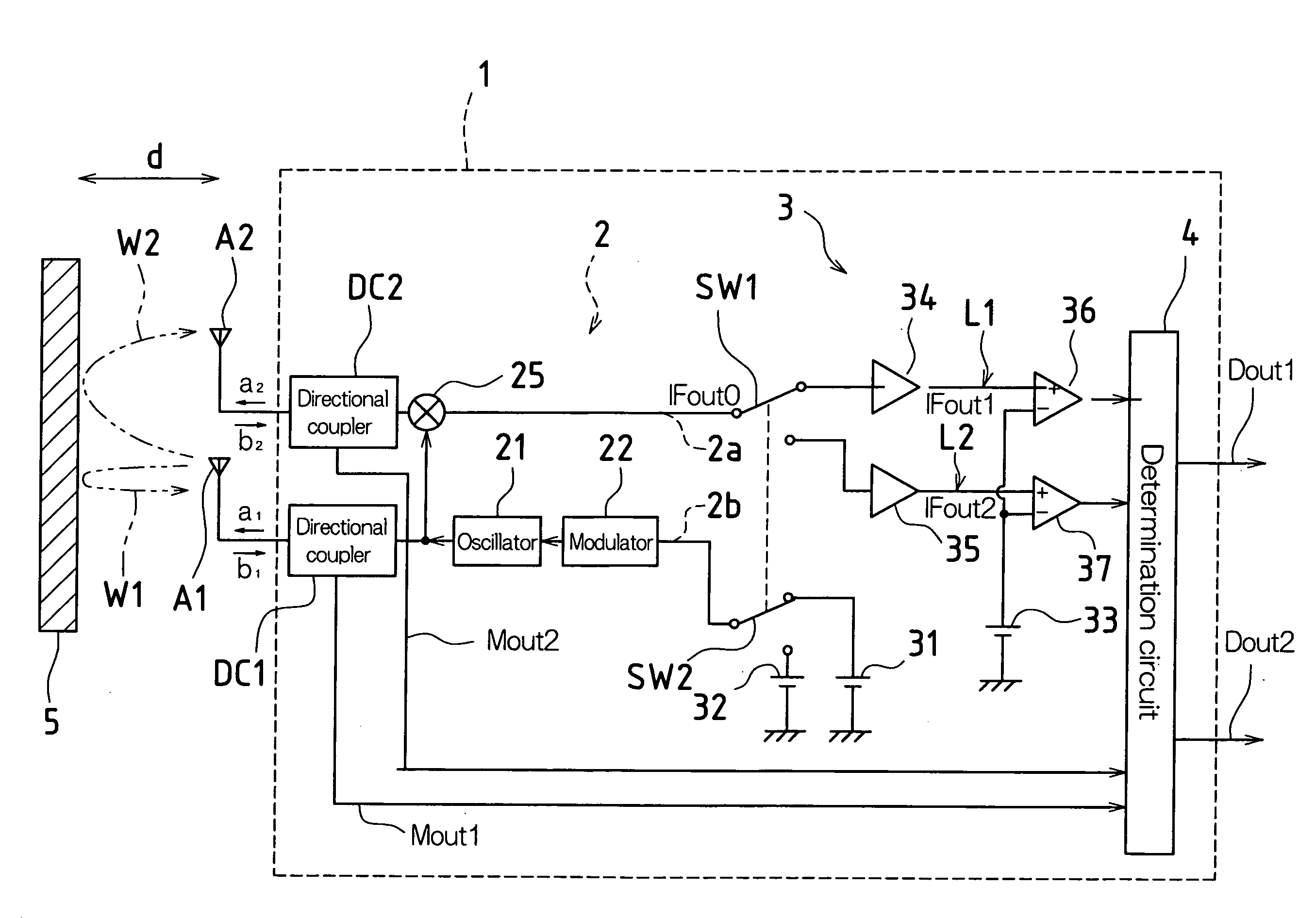
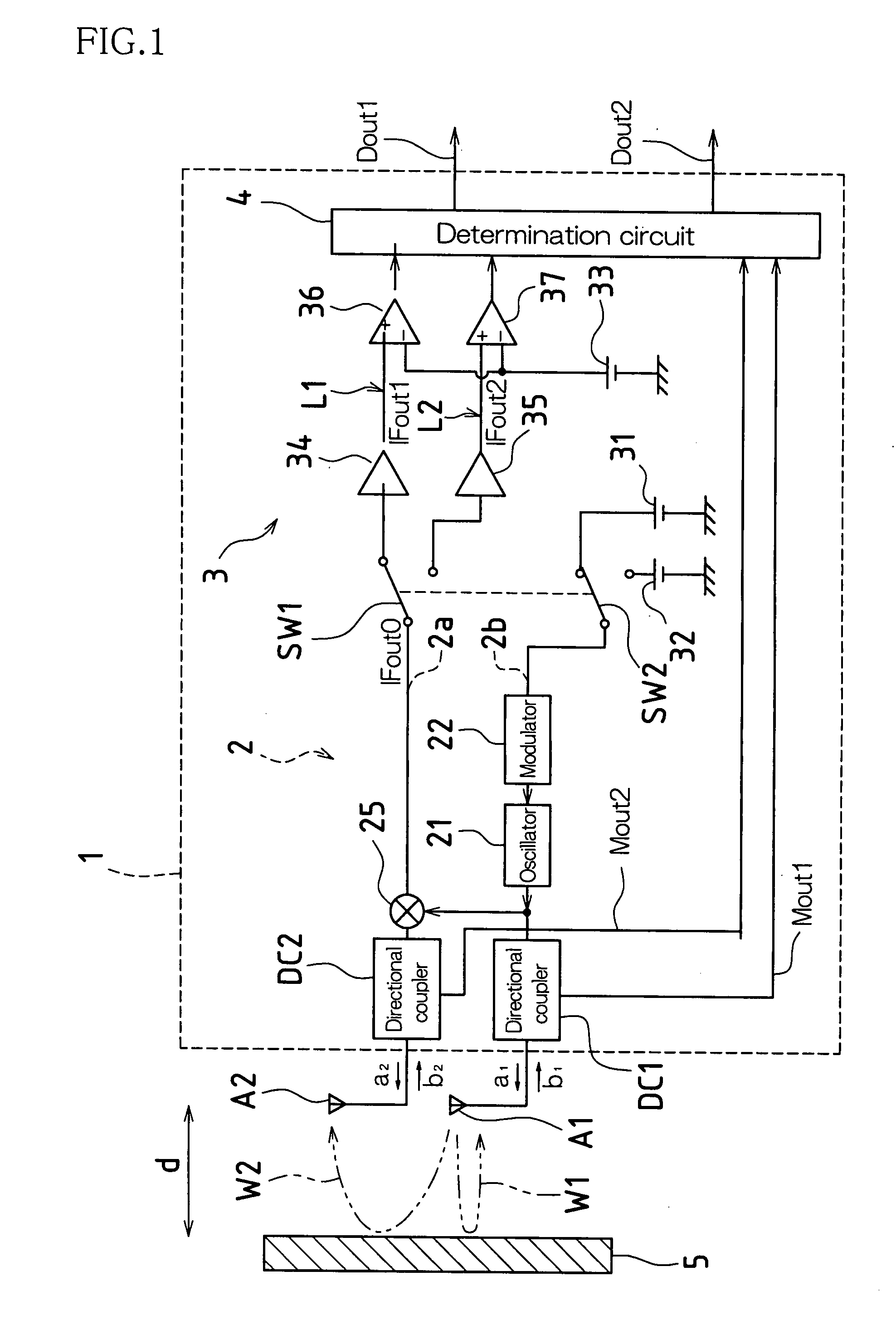
[0044]FIG. 1 is a schematic diagram of the configuration of a microwave sensor 1 according to an embodiment of the present invention. As shown in FIG. 1, a microwave sensor 1 includes an RF module 2 that performs transmission and reception of microwaves, a signal processing unit 3 that processes a signal output from the RF module 2, and a determination circuit 4 that detects a human body or the like based on the output from the signal processing unit 3 and detects masking or the like based on scattering parameters detected by the RF module 2.

[0045]The RF module 2 is provided with an oscillator 21 that generates microwaves, a modulator 22 for switching the frequencies of microwaves generated by the oscillator 21, a transmission antenna A1 that transmits the microwaves generated by the oscillator 21 toward a detection area...


PUM


Abstract

According to one embodiment, a microwave sensor includes: a first directional coupler (DC1) connected on a path of a transmission antenna unit (A1); a second directional coupler (DC2) connected on a path of a reception antenna unit (A2), and a determination unit (4) that obtains, based on monitor outputs from these, a scattering parameter S11 corresponding to a reflectance property at the transmission antenna unit (A1) and a scattering parameter S21 corresponding to a transmission property from the transmission antenna unit (A1) to the reception antenna unit (A2), and outputs an alarm signal (Dout2) when at least one of the scattering parameter S11 and the scattering parameter S21 continuously exhibits a value outside its respective pre-set range over a predetermined period of time.

Description

TECHNICAL FIELD[0001]The present invention relates to a microwave sensor that detects an intruder or the like by microwaves, and particularly to a microwave sensor capable of countering measures such as masking using a metal plate or the like.BACKGROUND ART[0002]Conventionally, as one form of a crime prevention sensor, microwave sensors are known (see Patent Document 1, for example) in which microwaves are emitted toward a detection area, and when a human body (an intruder) is present in the detection area, the human body is detected by receiving the reflected waves (microwaves modulated due to the Doppler effect) from the human body.[0003]Moreover, one type of microwave sensor is known that uses a plurality of microwaves of different frequencies to measure the distance to an object (hereinafter referred to as “target”) such as a human body that is present in the detection area. This type of sensor emits, for example, two microwaves of different frequencies toward the detection area...

Claims


Application Information

Patent Timeline
IPC IPC(8): G08B13/18
CPCG01S7/40G08B13/2491G01V3/12G01S13/04
Inventor TSUJI, MASATOSHI
Owner OPTEX CO LTD
Learn More