
Data throttling circuit and method for a spacewire application

Active Publication Date: 2008-07-10
CAES COLORADO SPRINGS LLC
View PDF3 Cites 3 Cited by
  • Summary
  • Abstract
  • Description
  • Claims
  • Application Information

AI Technical Summary

Benefits of technology

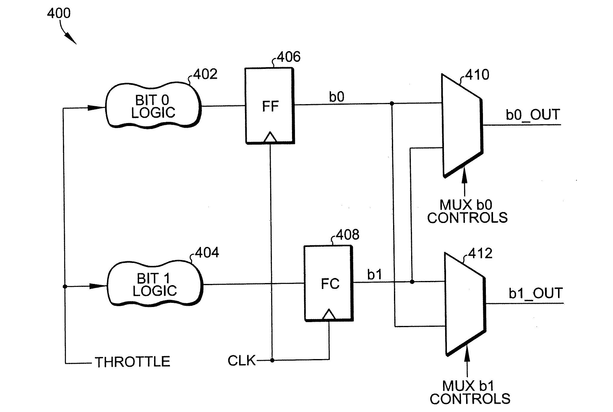
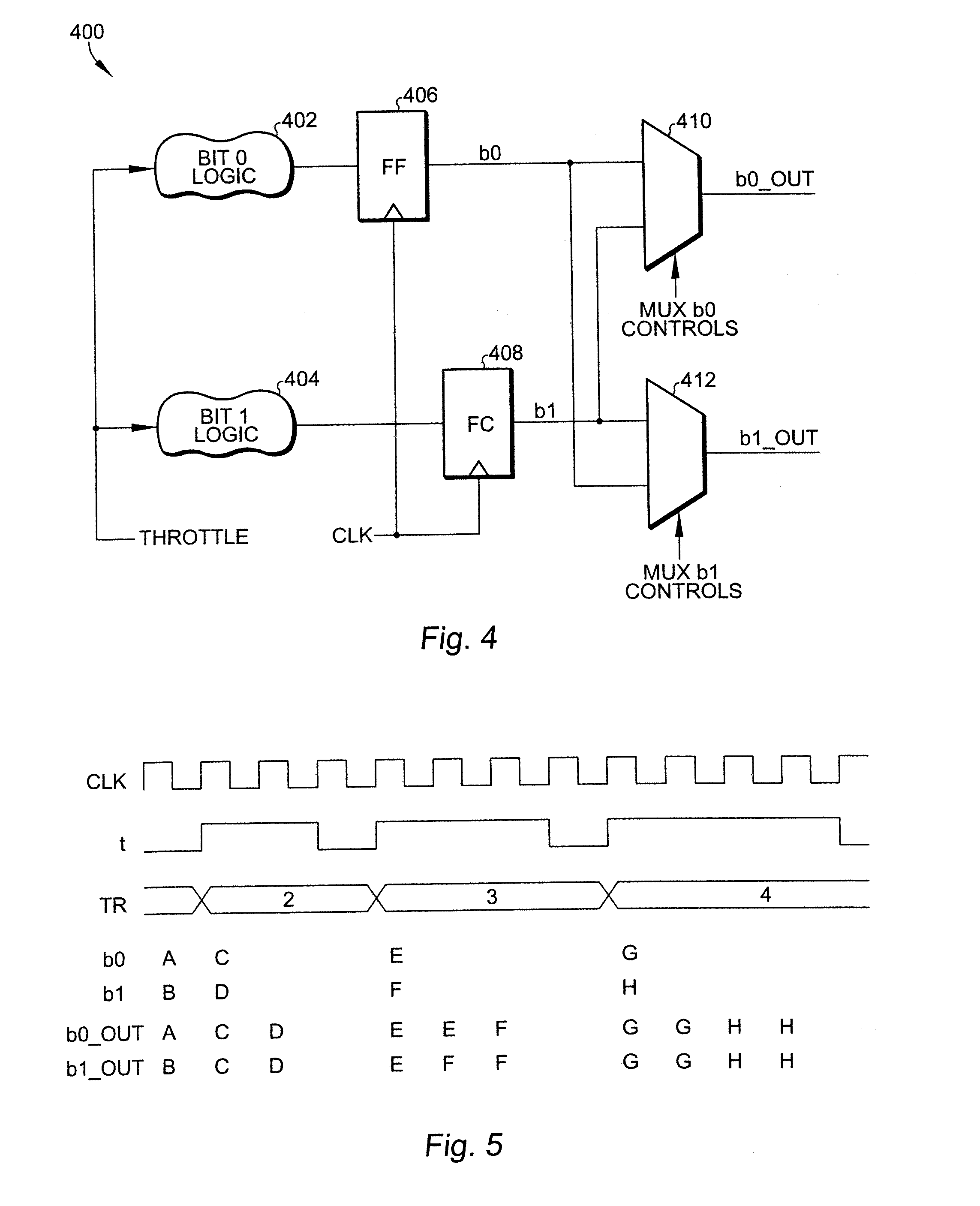
[0006]An object of the present invention is to duplicate the full-speed transmission of data so that it appears to be transmitting at a 10 Mhz rate. For example a logic one at 100 Mhz is sent ten times to appear to be a logic one at 10 Mhz. Implementing the approach of the present invention involves adding additional storage elements and multiplexers along the data path but completely eliminates undesirable complexity in the clock tree. A slight complication is addressed by the present invention for multiple-bit applications. In a two-bit application, data is received and transmitted two bits at a time, and yet the output 10 Mhz data rate must be maintained. In a “normal” situation in which there is an even ratio between the system clock rate and the 10 Mhz clock signal rate, Bit0 is transmitted for half the time and bit1 is transmitted for the other half of the time. But if the full-speed clock rate is an odd multiple of 10 Mhz, then there will be a “split cycle” according to the present invention. For example if the full-speed clock rate is 150 Mhz, and the data to be sent is a “1-0” data pair, then, according to the present invention, there are seven transmissions of a “1-1” data pair, one transmission of a “1-0” data pair, and seven transmissions of a “0-0” data pair.

Problems solved by technology

This method proved to be unworkable when used in an FPGA implementation and when coupled with an additional requirement to drive this qualified clock off-chip.
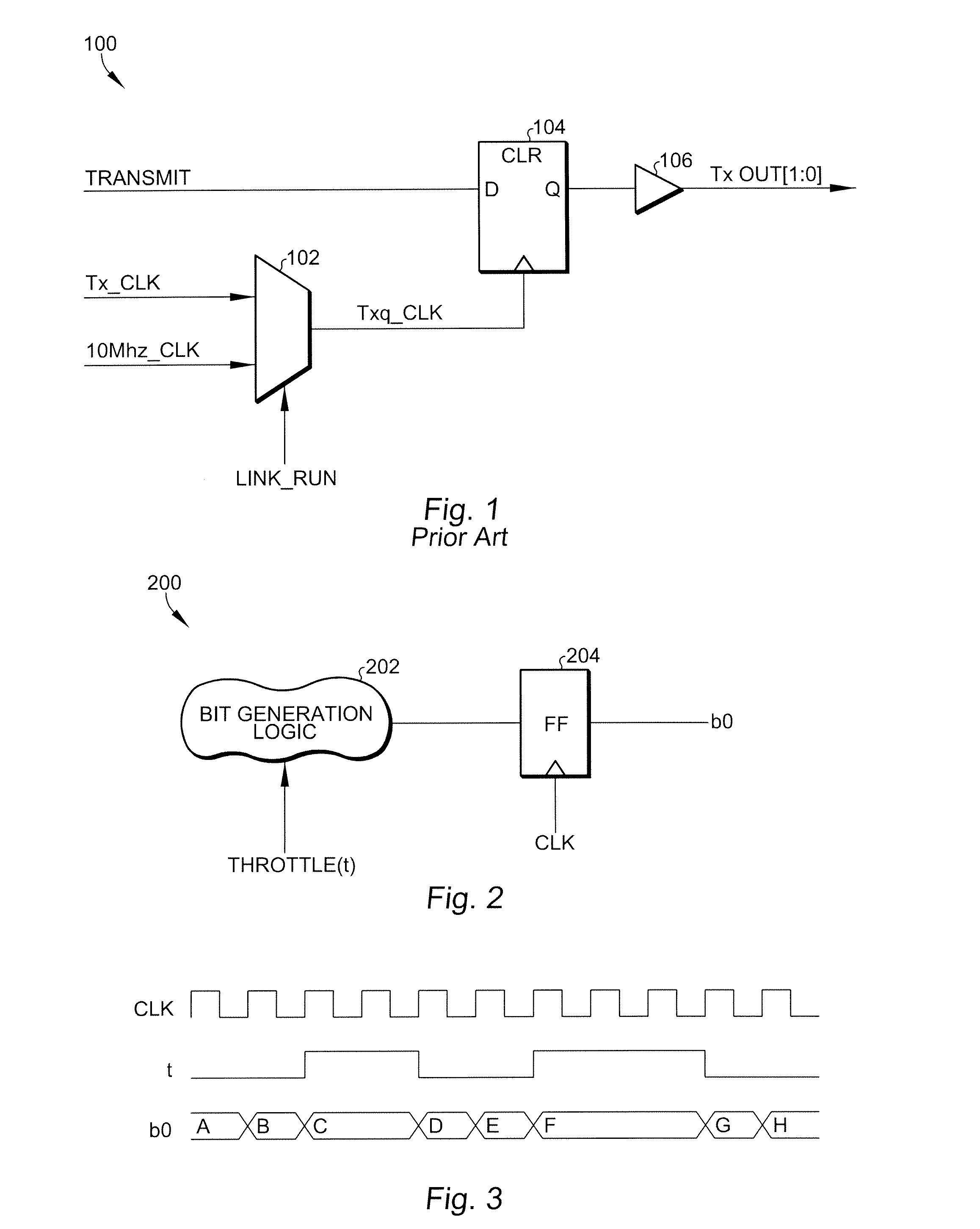
Note that in FIG. 1, circuit 100 includes a multiplexer 102 in the clock path, complicating the clock tree and making FPGA implementation difficult.

Method used


Image

  • Data throttling circuit and method for a spacewire application
  • Data throttling circuit and method for a spacewire application
  • Data throttling circuit and method for a spacewire application

Examples


Embodiment Construction

[0015]Referring now to FIG. 2 a basic one-bit Data Throttling circuit 200 is shown, including bit generation logic 202 for receiving a throttle signal coupled to a flip-flop 204 for receiving a CLK signal and providing a signal bit “bit0” data output. In an “open throttle” condition in which the throttle control signal is set to a logic zero, the output data changes for every CLK cycle. In a “closed throttle” condition current data is held until the throttle control signal is released. No other logic or programming support is required for the simple one-bit data throttling shown in FIG. 1, other than the throttle control waveform and the CLK clock signal.

[0016]Referring now to FIG. 3, a timing diagram is shown for the Data Throttling circuit 200 of FIG. 2. The timing diagram includes the CLK clock signal, and a representative throttle signal “t”. Note that when the throttle signal “t” is low, the output data changes state on every leading edge of the CLK signal. Alternatively, when ...


PUM


Abstract

A Data Throttling method duplicates the full-speed transmission of data so that it appears to be transmitting at a 10 Mhz rate. Additional storage elements and multiplexers are added along the data path but this completely eliminates undesirable complexity in the clock tree. In a two-bit application, data is received and transmitted two bits at a time, and yet the output 10 Mhz data rate is maintained. For an even ratio between the system clock rate and the 10 Mhz clock signal rate, bit0 is transmitted for half the time and bit1 is transmitted for the other half of the time. But if the full-speed clock rate is an odd multiple of 10 Mhz, then there will be a “split cycle” including one bit0 and one bit1.

Description

BACKGROUND OF THE INVENTION[0001]The present invention is related to data transmission, and, more particularly, to transmitting data at a rate slower than a system clock signal speed during link initialization in conformance with a SpaceWire application.[0002]SpaceWire is the common name associated with the European Cooperation For Space Standardization Specification ECSS-E-50-12A. According to this specification the data rate on the wire must be slowed down to 10 Mhz during link initialization. Data Throttling is a way to meet this requirement without having to adjust the transmit clocks.[0003]Prior auto-detect art has been developed that involves on-chip generation of a 10 Mhz clock, multiplexing with the full speed clock to create a qualified clock, and distribution of this clock on a dedicated clock network. This method proved to be unworkable when used in an FPGA implementation and when coupled with an additional requirement to drive this qualified clock off-chip. Data Throttli...

Claims


Application Information

Patent Timeline
IPC IPC(8): H03M7/00
CPCH04L47/10
Inventor GRIFFITH, J. STEVEPFEIL, JOHNSTRATTON, SAM
Owner CAES COLORADO SPRINGS LLC
Learn More