Image Recognition and Analysis System and Software

a technology of image recognition and analysis system, applied in the field of image recognition computer software, can solve the problems of consuming oxygen in the culture, causing a large amount of foam in the headspace of the vessel, and affecting the quality of the imag

Inactive Publication Date: 2008-07-10
POLLACK LAB
View PDF52 Cites 29 Cited by
  • Summary
  • Abstract
  • Description
  • Claims
  • Application Information

AI Technical Summary

Benefits of technology

[0013]These visual observations can also be compared and used with like observations obtained from other areas within the same process and vessel or from observations from other processes and vessels. For example, the differences in the results provided by changing a process parameter can be readily determined from such a comparison and analytical results of future processes can therefore be better anticipated. Accordingly, the use of the vision probes and software not only yield additional information about an on-going process but also can be to demonstrate the interaction between various analytical methodologies.

Problems solved by technology

Problems often arise with respect to the injection of gas into a process liquid.
For example, if the size, volume, quantity, or injection rate of bubbles and / or parameters, such as bubble size versus volume, is too great, a significant quantity of the bubbles reach the surface of the process liquid without being absorbed and creates an undesirable amount of foam in the headspace of the vessel.
The presence of too much foam can effectively close off the upper surface of the process liquid, thereby starving the culture of oxygen, and / or can clog filters.
Problems can also occur if the size, volume, quantity, or injection rate of bubbles and / or parameters, such as bubble size versus volume, is too small.
In this case, only localized areas of the process liquid is sufficiently aerated and an overall sufficient amount of absorption and uniform absorption fail to occur.
Problems are also presented by the agitator.
If the blades of the agitator rotate too swiftly, bubbles of an undesirable large size may be generated, too much turbulence may be generated, and too much foam may be caused to form in the headspace.

Method used


Image

  • Image Recognition and Analysis System and Software
  • Image Recognition and Analysis System and Software
  • Image Recognition and Analysis System and Software

Examples


Embodiment Construction

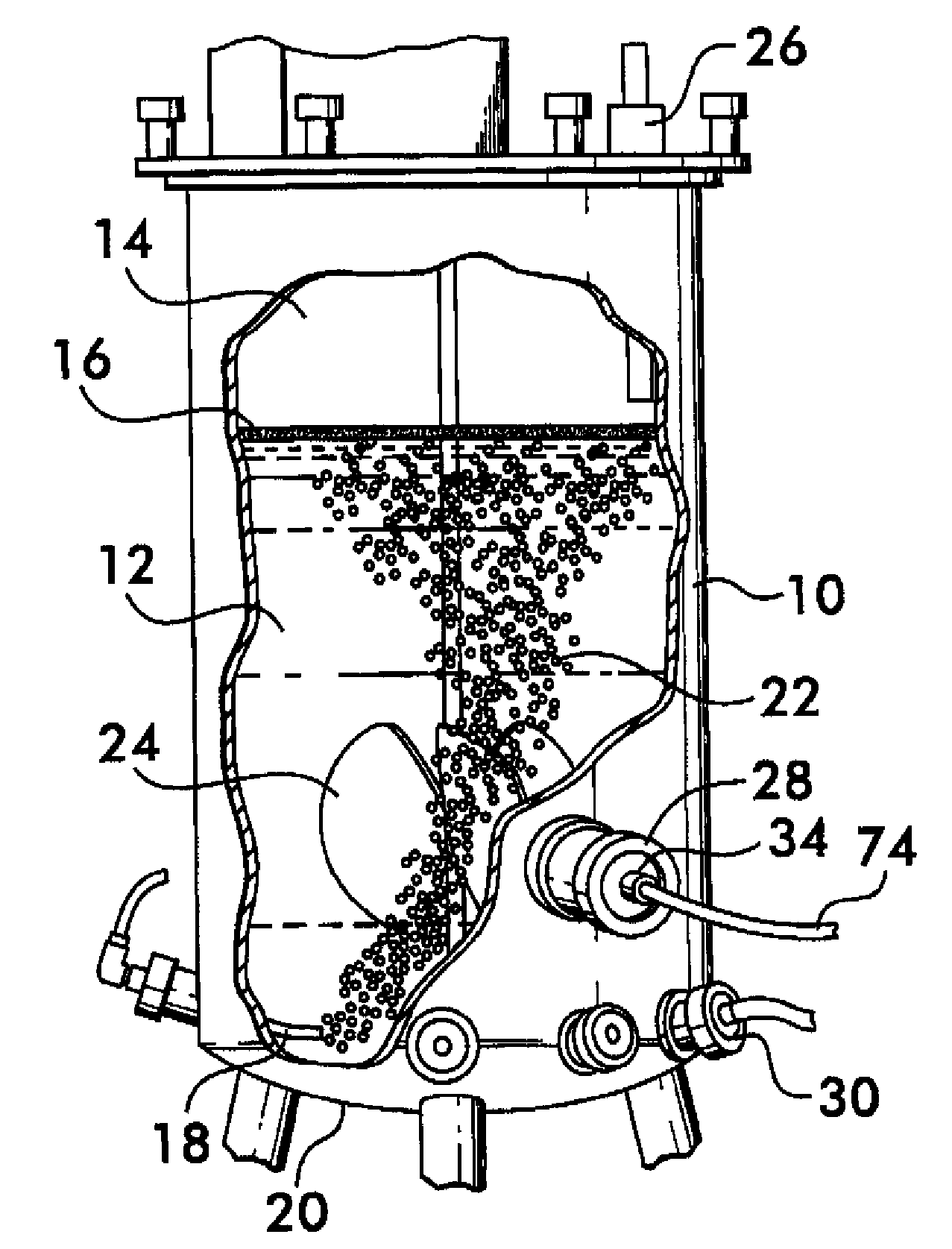
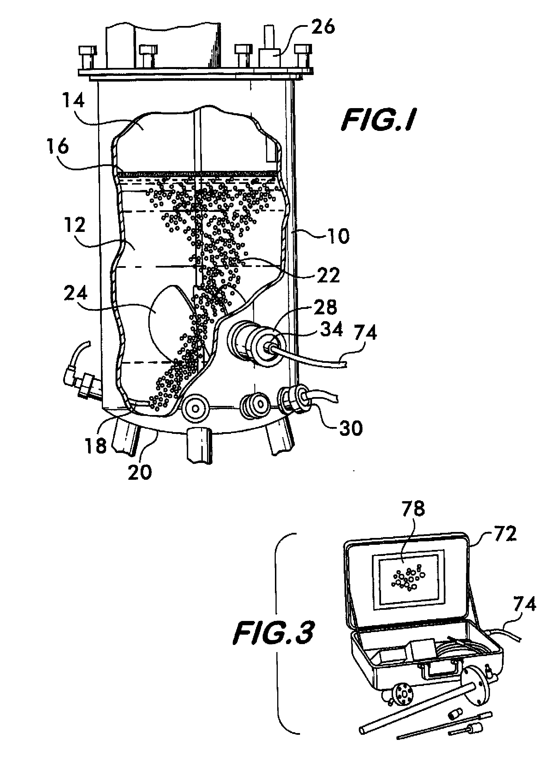
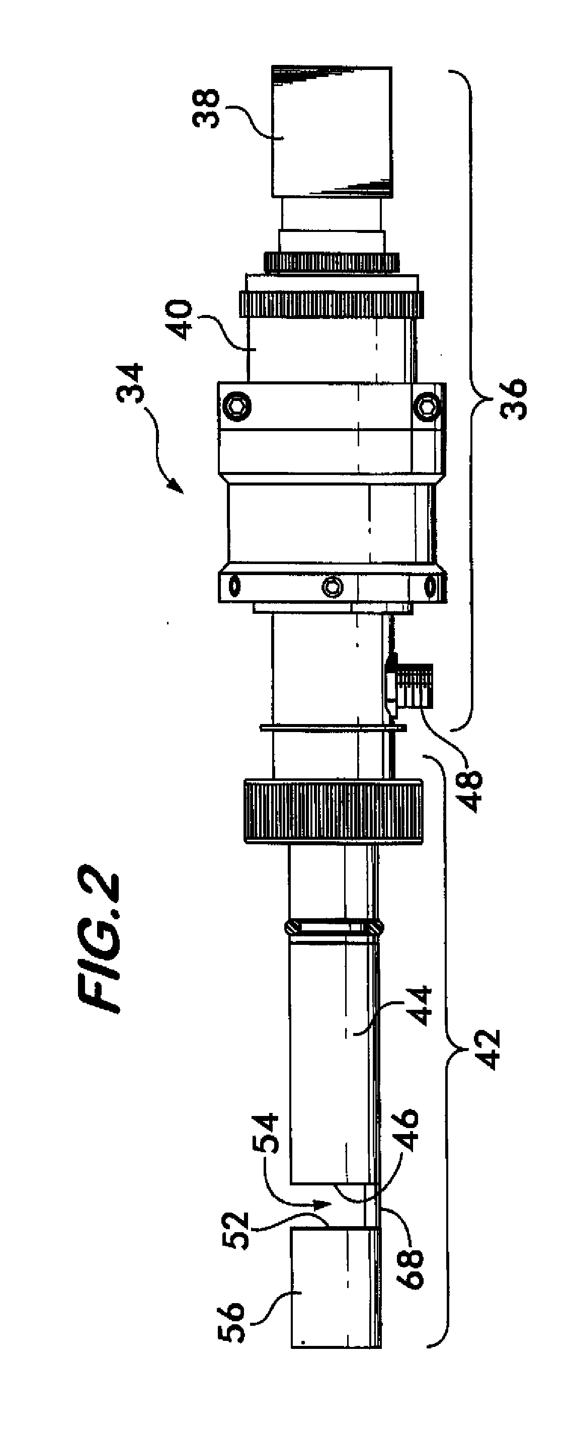
[0028]The present invention relates to a system and method for analyzing bubbles, cells, or other small particles in a process liquid. For example, gas released from a sparger within a process liquid contained in a vessel may be observed in-situ with at least one vision probe extending through one or more access ports in the walls of the vessel. The gas bubbles within the process liquid may be distributed and sheared within the liquid by an agitator located adjacent the sparger. The vessel may have multiple access ports located at different locations for enabling different areas within the vessel to be observed. The vision probes are mounted within the access ports and may include interchangeable parts, such as cameras, lens assemblies, sensors, light guides, light sources, etc., permitting a desired observation to be obtained.

[0029]The bubbles, cells, or other particles are observed by projecting light from the vision probe into the vessel to illuminate the gas bubbles, cells, or o...


PUM


Abstract

A method of analyzing bubbles, cells, cell viability, or other particles or agglomerates in a process liquid contained in a vessel is provided. Images of bubbles, cells or other particles in the liquid are obtained in-situ with a vision probe extending through a wall of the vessel. The images are analyzed with image recognition software. The software measures at lease one of bubble, cell or particle size, mean diameter, surface area, flow rate, flow pattern, population distribution, viability, agglomerates or clumping, color change, viscosity, Sauter mean, ratio of surface area of bubbles relative to volume of bubbles, gas hold-up ratio of gas volume to volume of liquid, or interfacial area. The software distinguishes valid or viable bubbles, cells or particles that should be included in an analysis from invalid or non-viable bubbles, cells or particles that should not be included. The software can be configured to provide an analysis of the valid bubbles, cells or particles that fall within pre-set size and shape or viability parameters.

Description

CROSS-REFERENCE TO RELATED APPLICATION[0001]This application claims the benefit under 35 USC §119(e) of U.S. Provisional Patent Application No. 60 / 883,829, filed Jan. 8, 2007.BACKGROUND OF THE INVENTION[0002]The present invention relates to image recognition computer software and the use thereof to analyze images of bubbles or particles, and more particularly, the present invention relates to a system of observing and analyzing a process occurring within a vessel.[0003]The production of biopharmaceuticals, enzymes and other biotechnology derived compounds typically takes place in a vessel, such as a bioreactor, fermenter, or the like. As an example, a vessel may include a sparger for introducing a gas, such as compressed air, directly within the liquid in the form of bubbles. The bubbles are typically required to be of an appropriate size and volume and to be injected at an appropriate rate into the process liquid so that the gas is absorbed uniformly throughout the process liquid b...

Claims


Application Information

Patent Timeline
Patent Type & Authority Applications(United States)
IPC IPC(8): G06K9/00
CPCG01N15/0227G01N15/1463G01N21/8507G01N2015/0092G06T2207/30108G01N2015/1497G06T7/0002G06T2207/10016G06T2207/30024G01N2015/025
Inventor MANDRACHIA, STEVEN J.DARNELL, BRANSON J.REICHL, GARYPOLLACK, MICHAEL J.DIDOMIZIO, RICHARD A.
Owner POLLACK LAB
Why Eureka
Try Eureka