
Pixel Interpolating Method and Device

a pixel interpolation and pixel technology, applied in static indicating devices, computations using denominational number representations, instruments, etc., can solve the problems of circuit scale enlarged, limit regarding the high-speed processing of software processing and power consumption reduction, etc., to improve the speed of pixel interpolation processing and reduce power consumption.

Inactive Publication Date: 2008-07-10
SOVEREIGN PEAK VENTURES LLC
View PDF4 Cites 17 Cited by
  • Summary
  • Abstract
  • Description
  • Claims
  • Application Information

AI Technical Summary

Benefits of technology

[0027]An object of the present invention is to provide a pixel interpolating method and a pixel interpolating device, operable to improve the speed of pixel interpolating processing and to decrease the power consumption therein.
[0029]According to the present structure, when the absolute value of the pixel value difference of the adjoining pixel pairs is equal to or less than the predetermined value, the pixel interpolating method provided herein is operable to omit the processing of the second multiplication step pertaining to the pixel value difference of these adjoining pixels and the processing of addition or subtraction of the second product to the register. Therefore, the pixel interpolating processing can be performed at higher speed as much as a time otherwise needed for the omitted steps of processing.
[0039]According to the present structure, the pixel interpolating processing in conformity to H.264|MPEG-4 AVC can be performed efficiently and easily, by tap filtering with tap coefficients given by {1, −5, 20, 20, −5, 1}.
[0041]According to the present structure, when the absolute value of the pixel value difference of the adjoining pixel pair is equal to or less than the predetermined value, a pixel interpolating device provided herein is operable to omit the multiplication processing of the second multiplying unit pertaining to the pixel value difference of these adjoining pixels, and also operable to omit the pertaining processing of addition or subtraction of a plurality of adding / subtracting units. Therefore, when the pixel interpolating device according to the present structure is used, speedy generation of predicted pictures in motion compensation can be realized, owing to the reduction of the operation amount with accompanied suppressing effect in the power consumption.

Problems solved by technology

The interpolating processing needs to be performed as many as the number of the pixels included in the predicted blocks, furthermore, the predicted blocks include all the blocks for which inter-picture prediction is performed; therefore, the motion compensation processing requires a tremendous amount of operation in motion picture encoding or decoding.
In the pixel interpolating device in which the conventional pixel interpolation method is adopted as explained above, there is a limit regarding the high-speed processing in software processing and the power consumption reduction, because the operation amount is constant irrespective of the pixel values of reference pixels and no measure is taken for reducing the operation amount by considering the pixel values.
However, this method has a problem of the circuit scale enlarged as the result of installing the look-up table therein.
As explained above, the conventional pixel interpolating method and the conventional pixel interpolating device can not fully deal with the following problem.
However, in the conventional art, there is a limit for the processing speed; therefore, it is difficult to improve the speed of the motion compensation.
Moreover, when an art of motion picture encoding / decoding accompanied by such pixel interpolating processing is used for portable devices such as a cellular phone, decreasing the power consumption imposes another great concern, since there is a limit for the power supply used in these portable devices.

Method used


Image

  • Pixel Interpolating Method and Device
  • Pixel Interpolating Method and Device
  • Pixel Interpolating Method and Device

Examples


embodiment 1

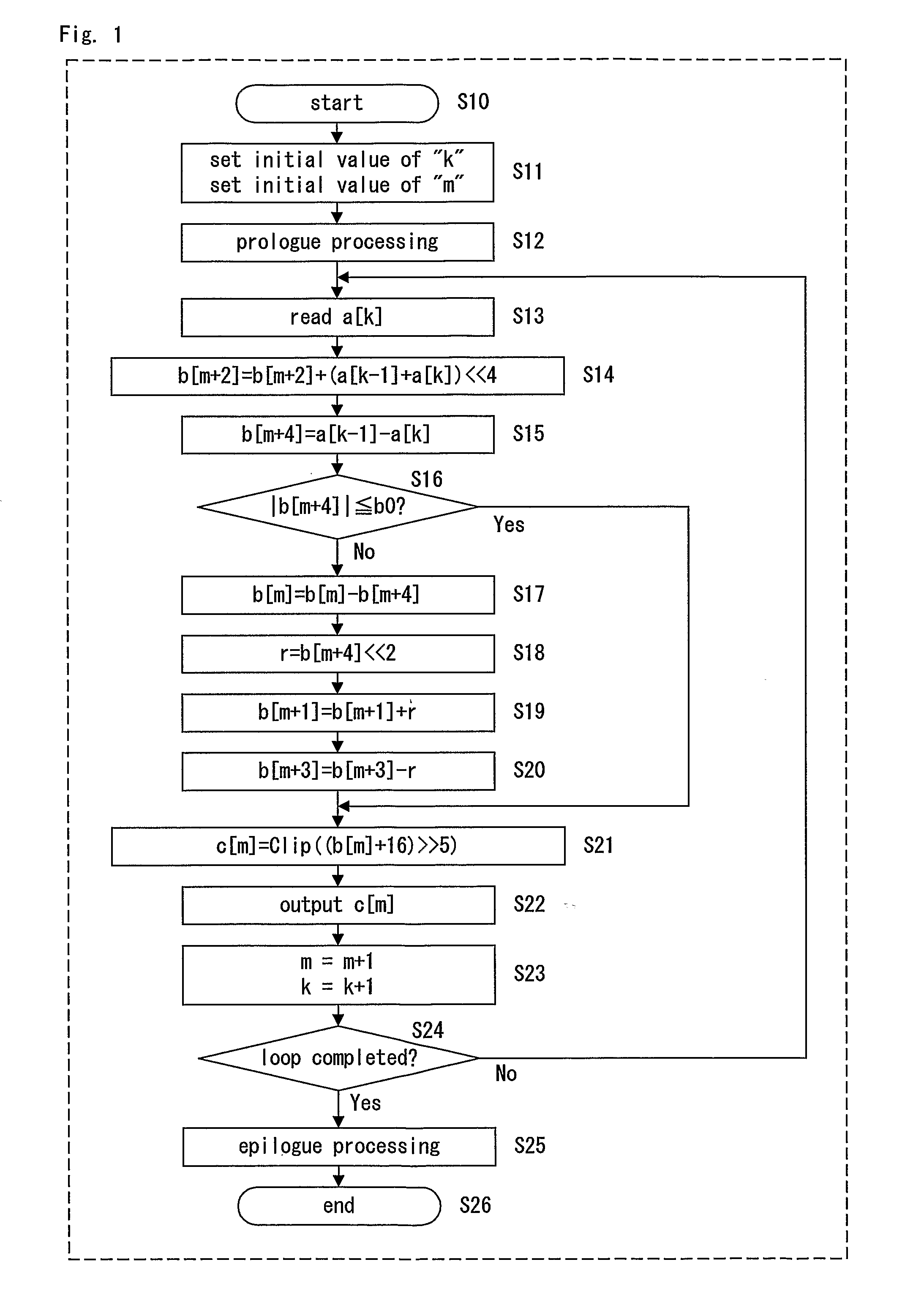
[0054]FIG. 1 is a flow chart of a pixel interpolating method in Embodiment 1 of the present invention. The flow chart shown in FIG. 1 is an example of the pixel interpolating method of the present embodiment.

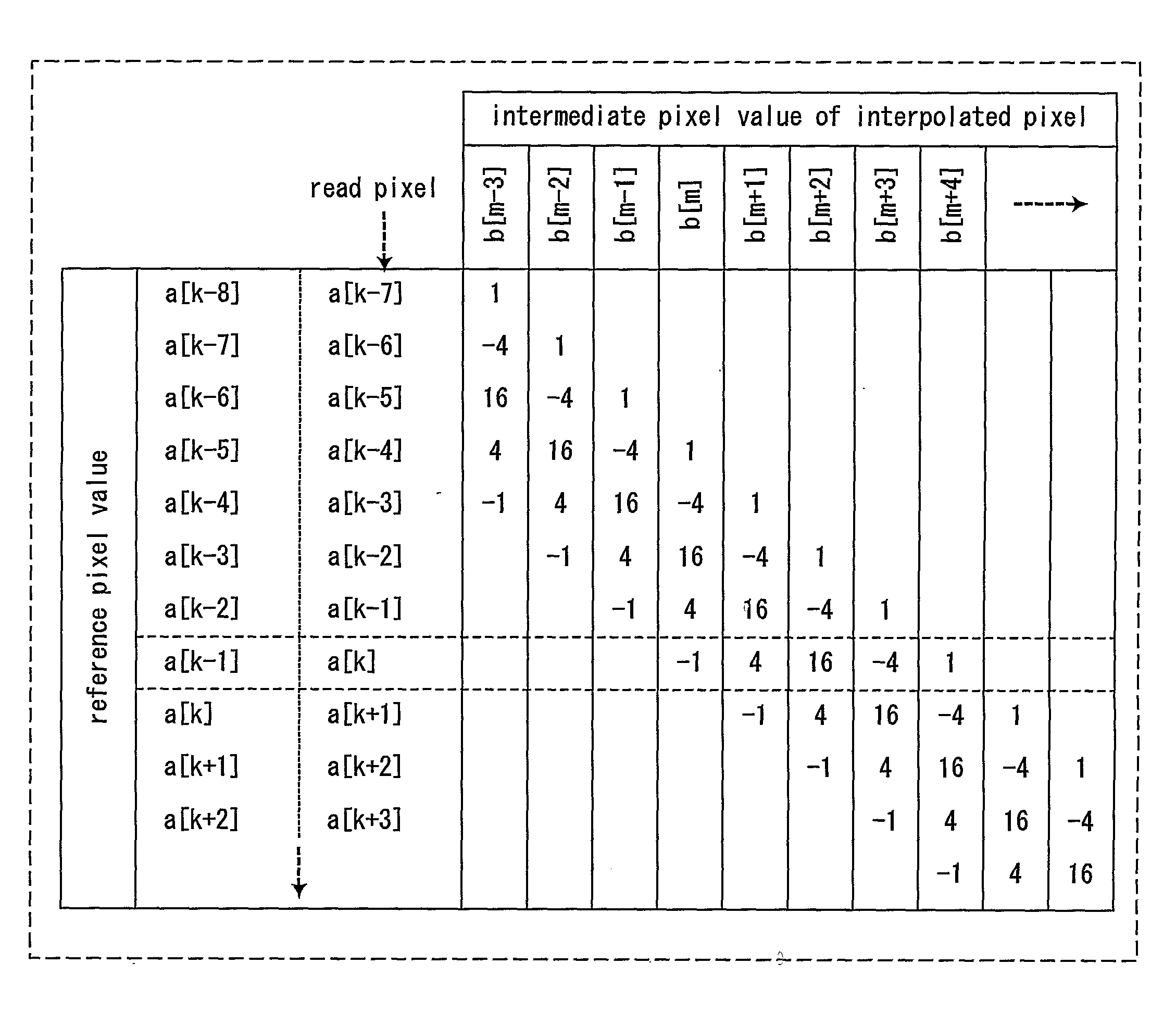
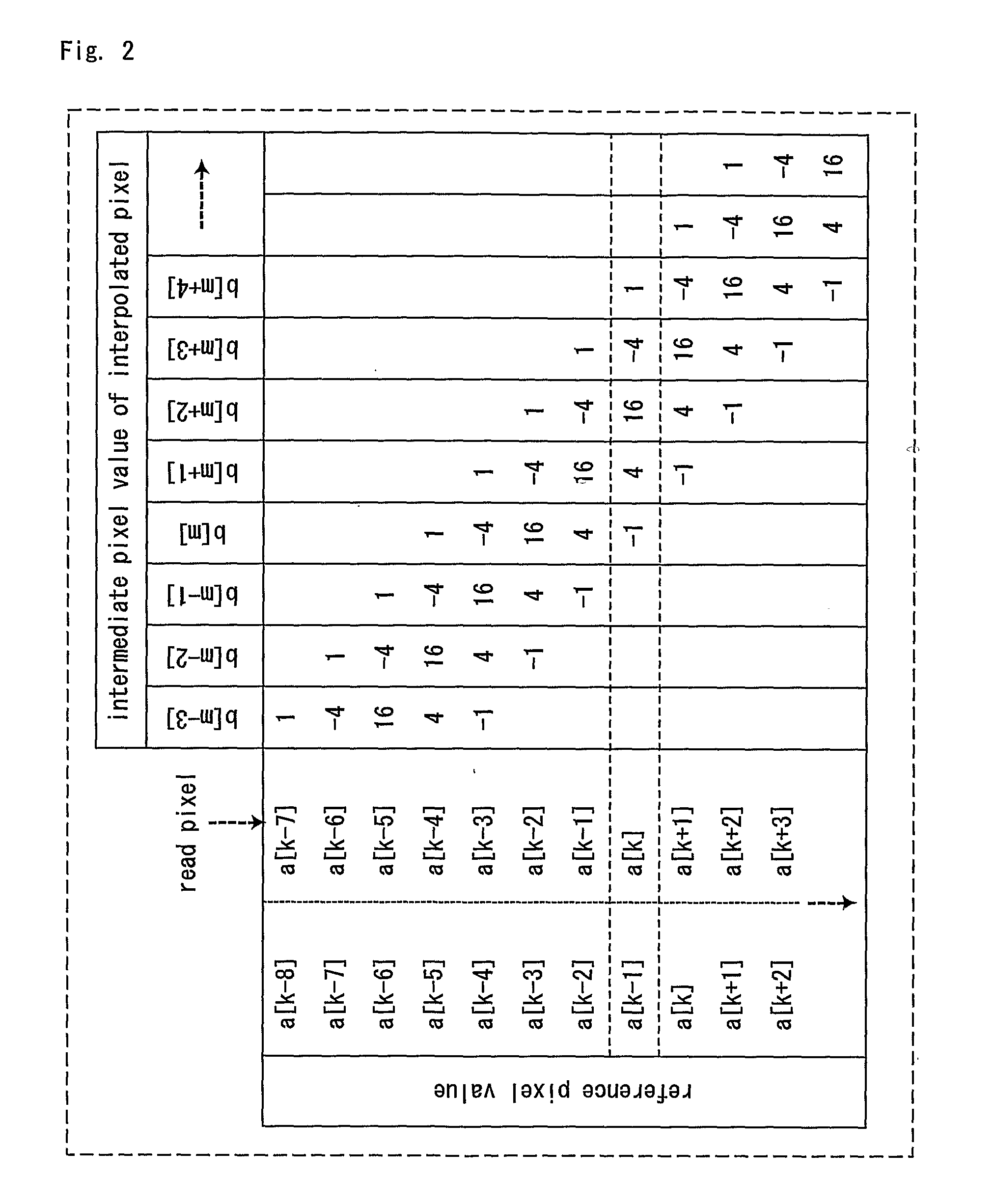
[0055]FIG. 2 is a descriptive illustration showing the pixel interpolating method in Embodiment 1 of the present invention.

[0056]First, basic ideas with which the present inventor has come up for the pixel interpolating method of the present embodiment are explained.

[0057]According to the pixel interpolating method of the present embodiment, the pixel value of an interpolated pixel is calculated by filtering pixel values of pixels of the reference picture with a 6-tap filter having tap coefficients {1, −5, 20, −5, 1}.

[0058]Assume that a[k] is the pixel value of a (k)th full-pel located at the (k)th position among pixels aligning on a horizontal or vertical line of the reference picture, and that a pixel value “c” is a pixel value of a half-pel to be interpolated, which is locate...

embodiment 2

[0098]FIG. 3 is a block diagram of a pixel interpolating device in Embodiment 2 of the present invention. The pixel interpolating device of the present embodiment practically performs the pixel interpolating method of the present invention described in Embodiment 1 of the present invention.

[0099]As shown in FIG. 3, the pixel interpolating device of the present embodiment comprises registers 11 to 16, adders 21 to 27, bit shifters 31 to 33, selectors 41 to 43, a comparator 51, a clipper 61, and constant units 71 and 72. In FIG. 3, the register is written as a symbol “R”, the adder as a symbol “+”, the bit shifter as a symbol “BS”, the selector as a symbol “SEL”, and the comparator as a symbol “C”.

[0100]In the following, operation of the pixel interpolating device of the present embodiment is explained.

[0101]In FIG. 3, the registers 11 to 16 are controlled by a control signal (not shown in the figure) in inputting data. From a plurality of reference pixels, the pixel value a[k] of the...

embodiment 3

[0117]FIG. 4 is a block diagram of a pixel interpolating device in Embodiment 3 of the present invention. The pixel interpolating device of the present embodiment is operable to process at once the picture data having the 16-bit structure, in which two pixel values having the 8-bit structure are packed.

[0118]Basically, the pixel interpolating device of the present embodiment is structured by arranging in parallel two pieces of the pixel interpolating device of Embodiment 2 of the present invention shown in FIG. 3 and omitting the common parts thereof. In other words, the pixel interpolating device of the present embodiment includes an upper part that determines the pixel values of the odd-numbered interpolated pixels, a lower part that determines the pixel values of the even-numbered interpolated pixels, and the other common parts. The upper part comprises registers 11, 14a, and 16a, adders 21a to 27a, bit shifters 31a to 33a, selectors 41a to 43a, a comparator 51a, a clipper 61a, a...


PUM


Abstract

The n-tap filtering for generating interpolated pixels is converted into calculation of terms consisting of the difference and sum of the pixel values of adjoining pixels. When the difference is equal to or less than a predetermined value, the calculation related to the terms including the difference is omitted, thereby reducing the calculation amount in generating the interpolated pixels. In loop processing according to a flow chart of the pixel interpolating method, the reference pixels are accessed by one pixel per one loop processing for reading pixel values thereof, and the difference and sum of the pixel values are calculate using the adjoining pixel value already read one loop before, thereby interpolating the pixel values of consecutive pixels to be interpolated. Consequently, redundant reading of pixel values is avoided, with further beneficial effects on speedy generation of the interpolated pixels and reduction of the power consumption therein.

Description

[0001]a predicted picture from a reference picture requires the interpolating processing of pixels, and the calculation method thereof is defined by each of the encoding standards.[0002]According to H.264, one of the encoding standards, 6-tap filtering as a method of the above-mentioned interpolating processing of pixels is specified by Document 1 (Joint Video Team (JVT) of ISO / IEC MPEG & ITU-T VCEG, “Draft ITU-T Recommendation and Final Draft International Standard of Joint Video Specification (ITU-T Rec.H.264|ISO / IEC 14496-10 AVC)”, refer to Section 8.4.2.2).[0003]The 6-tap filtering is explained briefly now. The 6-tap filter includes tap coefficients {1, −5, 20, 20, −5, 1}. Expressing a pixel value of a pixel at i-th location as a[i] (i: integer), among pixels aligned along a horizontal or vertical line on the reference picture, a pixel value for an interpolated pixel at (k+½)th location is calculated as follows. First, according to Equation 1, an intermediate pixel value “b” of ...

Claims


Application Information

Patent Timeline
IPC IPC(8): G06K9/32
CPCG06T3/4007
Inventor FUCHIGAMI, IKUO
Owner SOVEREIGN PEAK VENTURES LLC
Learn More