Passive optical network system and wavelength assignment method

a wavelength assignment and optical network technology, applied in the field of passive optical network system and wavelength assignment method, can solve the problem of difficulty for each onu to negotiate with the olt about which wavelength is used for communication, and achieve the effect of effective use and easy installation work

Inactive Publication Date: 2008-07-10
HITACHI LTD
View PDF13 Cites 92 Cited by
  • Summary
  • Abstract
  • Description
  • Claims
  • Application Information

AI Technical Summary

Benefits of technology

[0087]According to the invention, it is possible to provide a passive optical network system and a wavelength assignment method in which in a PON system of WDM, at the time of initial setting, each ONU negotiates with an OLT and automatically obtai

Problems solved by technology

For example, in the WDM-PON in which up to 32 ONUs can be connected, it is troublesome that at the installation of an ONU, an installer sets a wavelength other than those used in the OLT and the other ONUs.
However, i

Method used


Image

  • Passive optical network system and wavelength assignment method
  • Passive optical network system and wavelength assignment method
  • Passive optical network system and wavelength assignment method

Examples


first embodiment

1. First Embodiment

(System Structure)

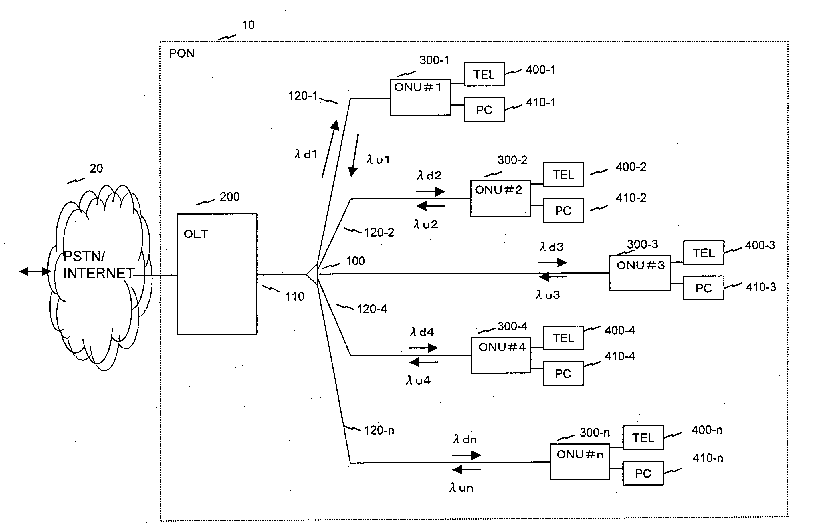
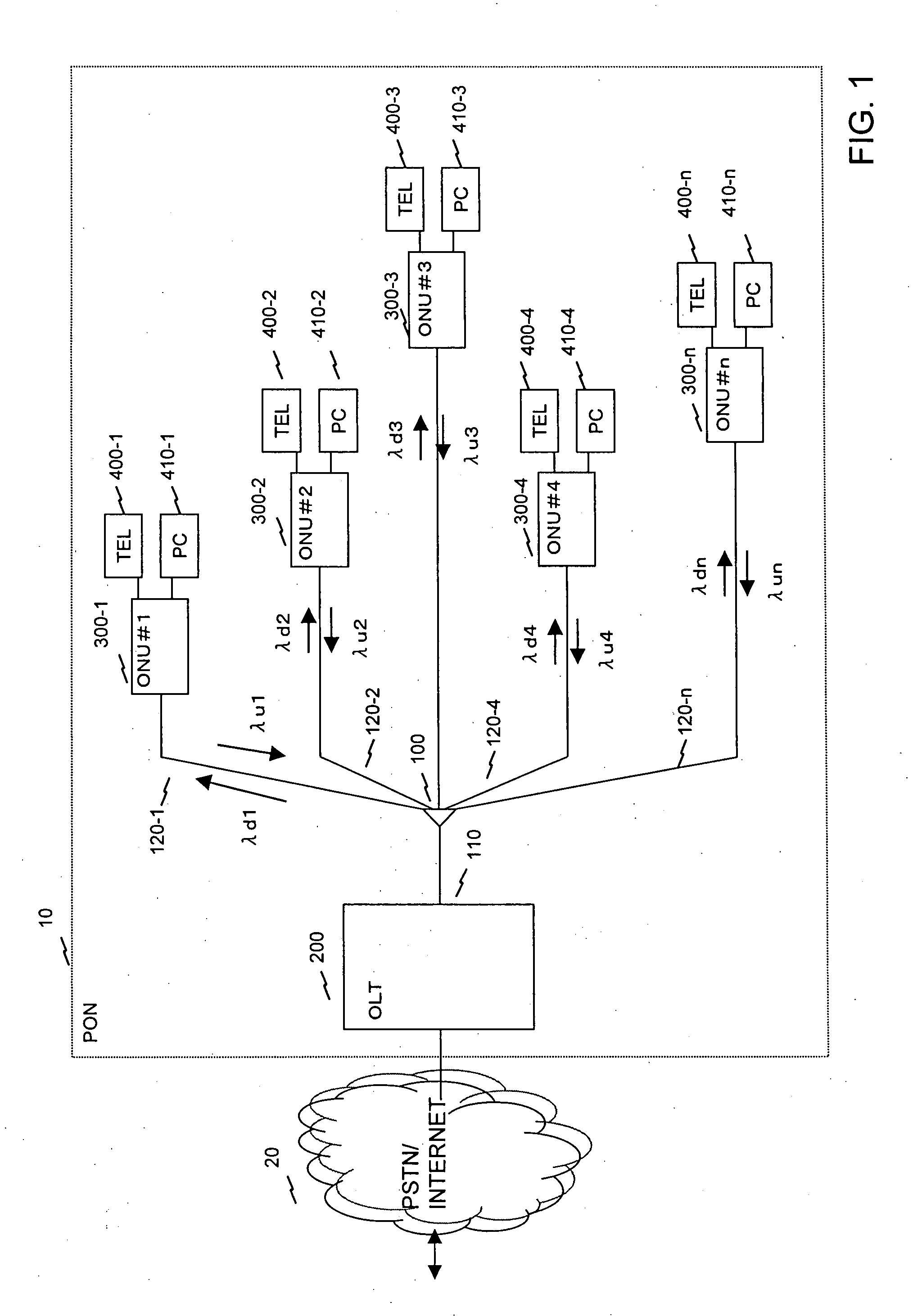
[0104]FIG. 1 shows a structure of an optical access network to which this embodiment is applied.

[0105]A PON 10 includes an optical splitter 100, a main fiber 110, plural subsidiary fibers 120, an OLT 200 and ONUs (or ONTs) 300. The PON 10 is connected to a PSTN / Internet 20, and transmits / receives data. For example, a telephone 400 and a personal computer 410 are connected to the ONU 300. For example, 32 ONUs 300 can be connected to the OLT 200 through the one main fiber 110, the optical splitter 100 and the subsidiary fibers 120. FIG. 1 shows five ONUs which are different from each other in wavelength used for communication with the OLT. In the illustrated example, the ONU 300-1 uses wavelengths λd1 and λu1, the ONU 300-2 uses λd2 and λu2, the ONU 300-4 uses λd4 and λu4, and the ONU 300-n uses λdn and λun. Incidentally, in this embodiment, λd denotes a wavelength of a downstream signal, and λu denotes a wavelength of an upstream signal. A signal ...

second embodiment

2. Second Embodiment

(System Structure)

[0168]FIG. 14 shows a structural example of an OLT 200 of this embodiment.

[0169]The difference from the structure of FIG. 3 is that, for example, a transmission enabling control unit 225 connected to a wavelength management table 220 is further provided, and a driver is not enabled for a wavelength the use of which is not registered in the wavelength management table 220, and light of a downstream wavelength is not emitted. For example, a driver of a downstream wavelength in which a serial number is not registered in the wavelength management table 220 is disabled. Accordingly, an ONU 300 monitors the presence or absence of a signal for each downstream wavelength, and can now which wavelength is unused.

[0170]FIG. 15 shows a structural example of the ONU 300 of this embodiment.

[0171]One of differences from the structure of FIG. 4 is that a reception power detection unit 326 is connected to an O / E 303. While referring to a timer 325, a CPU 323 cha...


PUM


Abstract

In a PON system with WDM, at the time of initial setting, each ONU negotiates with an OLT, and automatically acquires a wavelength which can be used by the ONU. One wavelength for negotiation of assigned wavelength is fixed as a default, and a newly connected ONU first uses the wavelength. The OLT 200 includes a plurality of light sources for downstream communication. The ONU 300 includes a wavelength variable filter selectively receiving one of wavelengths of downstream communication, and a wavelength variable light source selectively emitting light of one of plural wavelengths for upstream communication. The ONU 300 uses a transmission wavelength (for example, λu32) for negotiation and transmits a wavelength assignment request 1000 to the OLT 200. The OLT 200 selects a wavelength λu1 to be assigned from unused wavelengths, and transmits wavelength information to the ONU 300. The OLT 200 and the ONU 300 communicates using the notified wavelengths.

Description

BACKGROUND OF THE INVENTION[0001]The present invention relates to a passive optical network system and a wavelength assignment method, and particularly to a passive optical network system and a wavelength assignment method in which plural subscriber connection devices share an optical transmission line and communication is carried out by wavelength division multiplexing.[0002]A Passive Optical Network (PON) includes an Optical Line Termination (OLT) and plural Optical Network Units (ONU) or Optical Network Terminations (ONT) (hereinafter, these are also called optical network units). A signal, as an optical signal, from a terminal (PC etc.) connected to the ONU is optically multiplexed to an optical fiber to the OLT from the ONU through an optical fiber and an optical splitter and is sent to the OLT. After the OLT performs various signal processings, communication from a terminal of an ONU to a terminal of another ONU of the PON or communication with a terminal of a NW is carried ou...

Claims


Application Information

Patent Timeline
IPC IPC(8): H04J14/02H04B10/00H04B10/27H04B10/272H04J14/00H04L12/44
CPCH04J14/0226H04J14/025H04J14/0246H04J14/0282
Inventor KAZAWA, TOHRUSAKAMOTO, KENICHINISHINO, RYOSUKE
Owner HITACHI LTD
Why Eureka
Try Eureka