
Wave generating system

a technology of generating system and generating chamber, which is applied in the direction of wave producing pump, non-positive displacement fluid engine, non-positive displacement pump, etc., can solve the problem of inefficiency of releasing excess compressed air that produces inferior waves, small volume of pressurized air needed to achieve such effective operation in many embodiments, and inefficient release of excess compressed air, etc. problem, to achieve the effect of reducing or mitigating the effect of low pressure within the chamber

Inactive Publication Date: 2008-07-10
JOHNSON GARRETT TYLER
View PDF2 Cites 2 Cited by
  • Summary
  • Abstract
  • Description
  • Claims
  • Application Information

AI Technical Summary

Benefits of technology

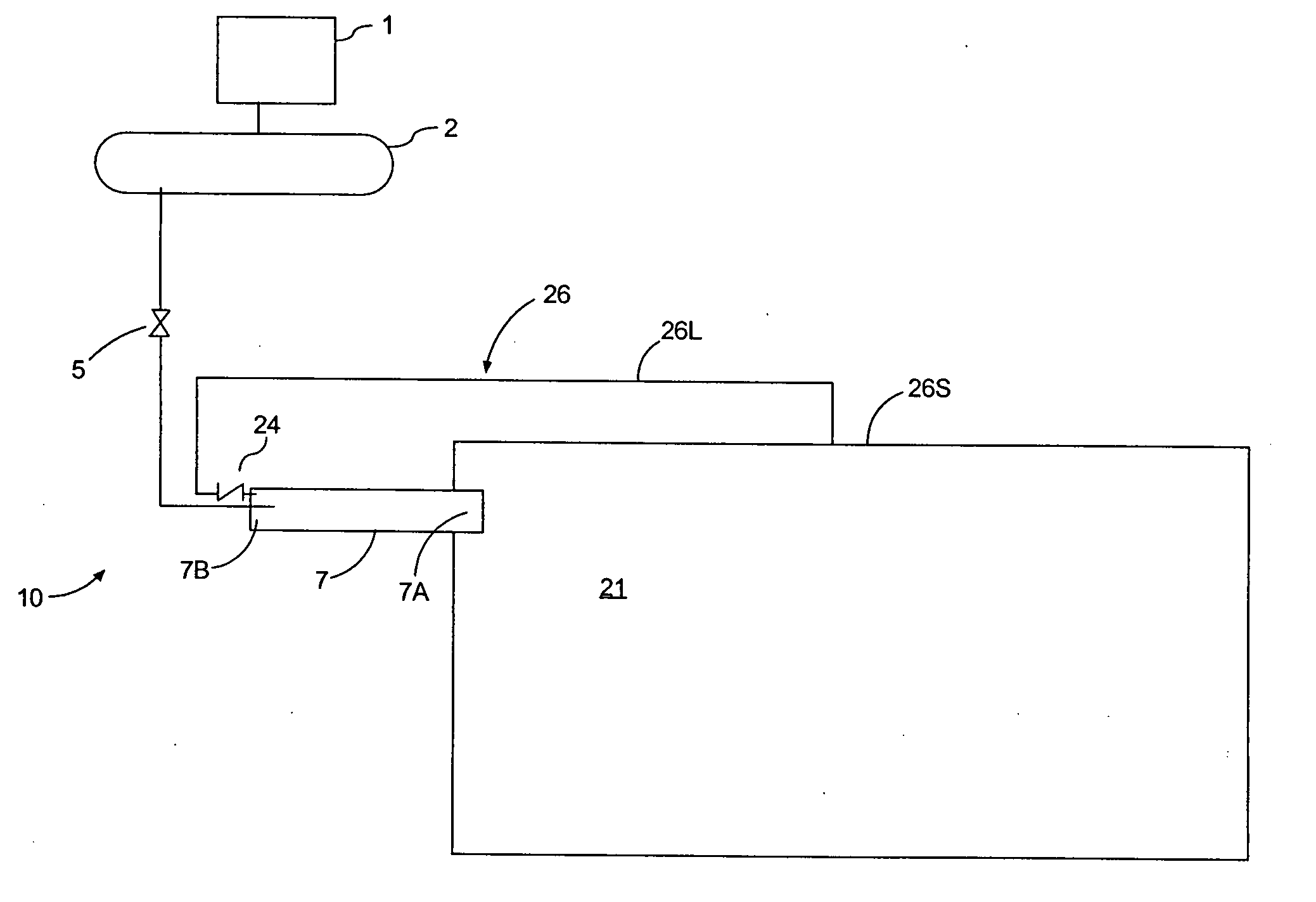
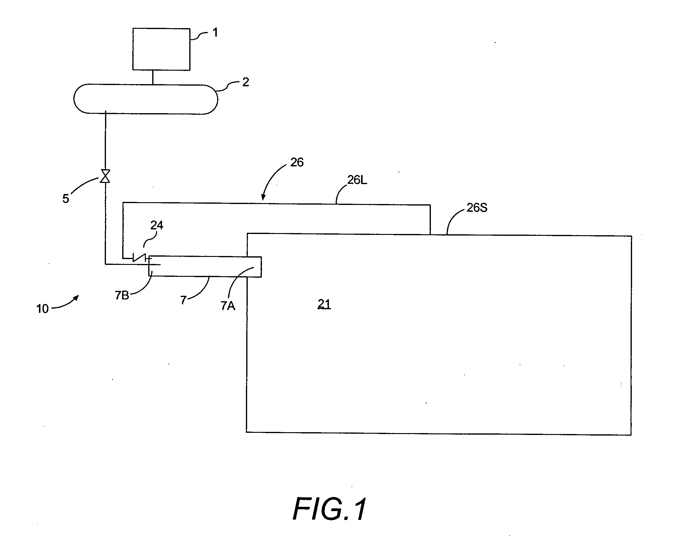
[0009]The present invention is a wave cannon that includes a system for improving efficiency by reducing or mitigating the effect of the low pressure within the chamber created by expelling water from the chamber.

Problems solved by technology

However, the volume of pressurized air needed to achieve such effective operation in many embodiments has proven to be somewhat expensive.
Such a partial discharge of water creates smaller, inferior waves.
Of course, a release of excess compressed air that produces inferior waves is inefficient.
Reducing the volume and / or pressure of air released has also been discovered to be potentially problematic.
If the air released is inadequate to discharge fully the water from the chamber, then depending on the pressure during discharge and that of the surrounding body of water, several problems can arise.
First, the inadequate discharge of water from the chamber can cause inferior or low quality waves.
Second, the discharge of water has been observed to be reverse, in some cases halting the flow outward and rapidly reversing flow direction so as to return back to the chamber with a significant impact.
When the once expelled water returns into the chamber, it creates a suction into the muzzle of the chamber, potentially posing a safety hazard to those in the wave pool.

Method used


Image

  • Wave generating system
  • Wave generating system
  • Wave generating system

Examples


Embodiment Construction

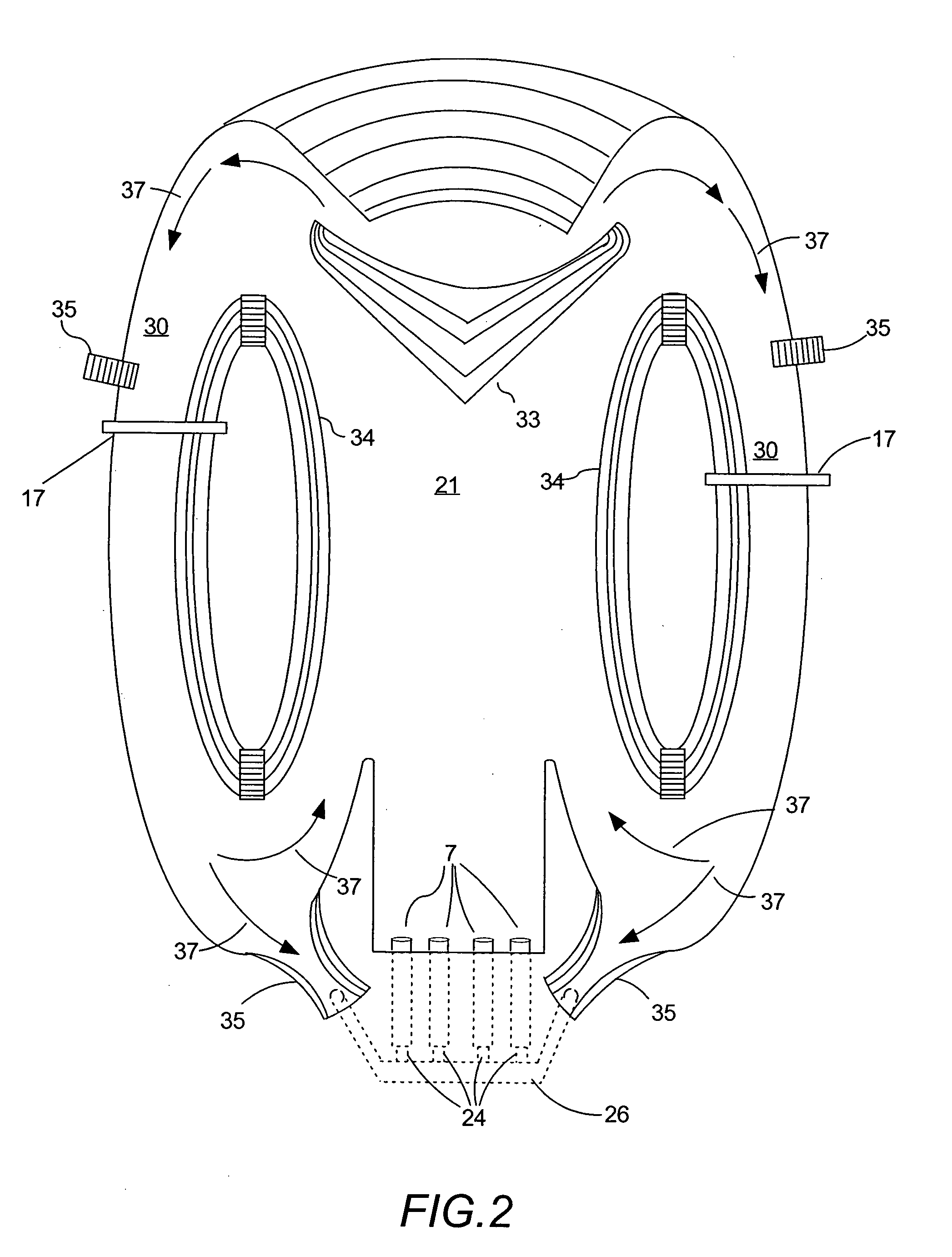
[0020]The present invention is a wave generating system. In particular, the present invention comprises a wave cannon that includes an additional system for improving efficiency and durability by reducing or mitigating the effect of the formation of low pressure within the discharge chamber, which can be created by the expulsion of water from the chamber.

[0021]The '393 patent generally disclosed that the volume of the pressurized air available should be equal to or greater than the combined volume of air that the elongated water chambers could contain. Col. 2, II. 52-54. In general, the release of compressed air that would discharge or expel all of the water from the chamber would generate an effective wave. However, the '393 patent did not disclose operational issues arising from the release of either too much or too little air into the chamber.

[0022]In general, the release of pressurized air creates a high pressure bubble within the rear or substantially closed end of the elongate...


PUM


Abstract

An improved device for discharging water that is capable of efficiently generating an effective wave-like motion within a body of water. Wave generation devices based on water filled elongated tubular chambers having a substantially closed rear end and a substantially open front end and using compressed air to discharge water, such as the wave cannon, may experience operational inefficiencies from variations in quantities of compressed air. Reducing the quantity of compressed gas may result in ineffective waves and damage to the elongated tube as internal low pressure conditions collapse. A source of make-up fluid configured to mitigate internal low pressure conditions can enable effective wave generation with reduced quantities of compressed air.

Description

CROSS REFERENCE TO RELATED APPLICATIONS[0001]The present application claims priority from U.S. Provisional Application Ser. No. 60 / 878,784, filed Jan. 6, 2007, which is hereby incorporated by reference.FIELD OF THE INVENTION[0002]The present invention relates to a wave generating system. More particularly, the present invention is a wave cannon having improved efficiency and durability.BACKGROUND OF THE INVENTION[0003]The wave cannon is a device described in U.S. Pat. No. 5,833,393 to Carnahan et al. ('393 patent), which is hereby incorporated by reference. The wave cannon generally relies on submerged, elongated chambers (e.g., tubes), which can be effectively or substantially open at one end and substantially closed at the other end.[0004]The wave cannon can create waves by releasing bursts of pressurized air that force water out of the chamber and into a body of water. The expelled water is generally a discrete volume defined by the chamber. As the water is forced out of the cham...

Claims


Application Information

Patent Timeline
Patent Type & Authority Applications(United States)
IPC IPC(8): F04D35/00
CPCF04D35/00
Inventor JOHNSON, GARRETT TYLER
Owner JOHNSON GARRETT TYLER
Learn More