
Tensioning roller device

a technology of tensioning rollers and rollers, which is applied in the direction of gearing, mechanical equipment, hoisting equipment, etc., can solve the problems of high cost of manufacture, high number of components, and high cost of assembly, and achieves the effects of simple and economical manufacturing and assembly, and extremely small amount of vibration

Inactive Publication Date: 2008-07-10
AB SKF
View PDF99 Cites 6 Cited by
  • Summary
  • Abstract
  • Description
  • Claims
  • Application Information

AI Technical Summary

Benefits of technology

[0008]The described embodiments are aimed at an automatic tensioning roller device, of simple and economical design, including a low number of component parts and avoiding the generation of vibration or premature wear.
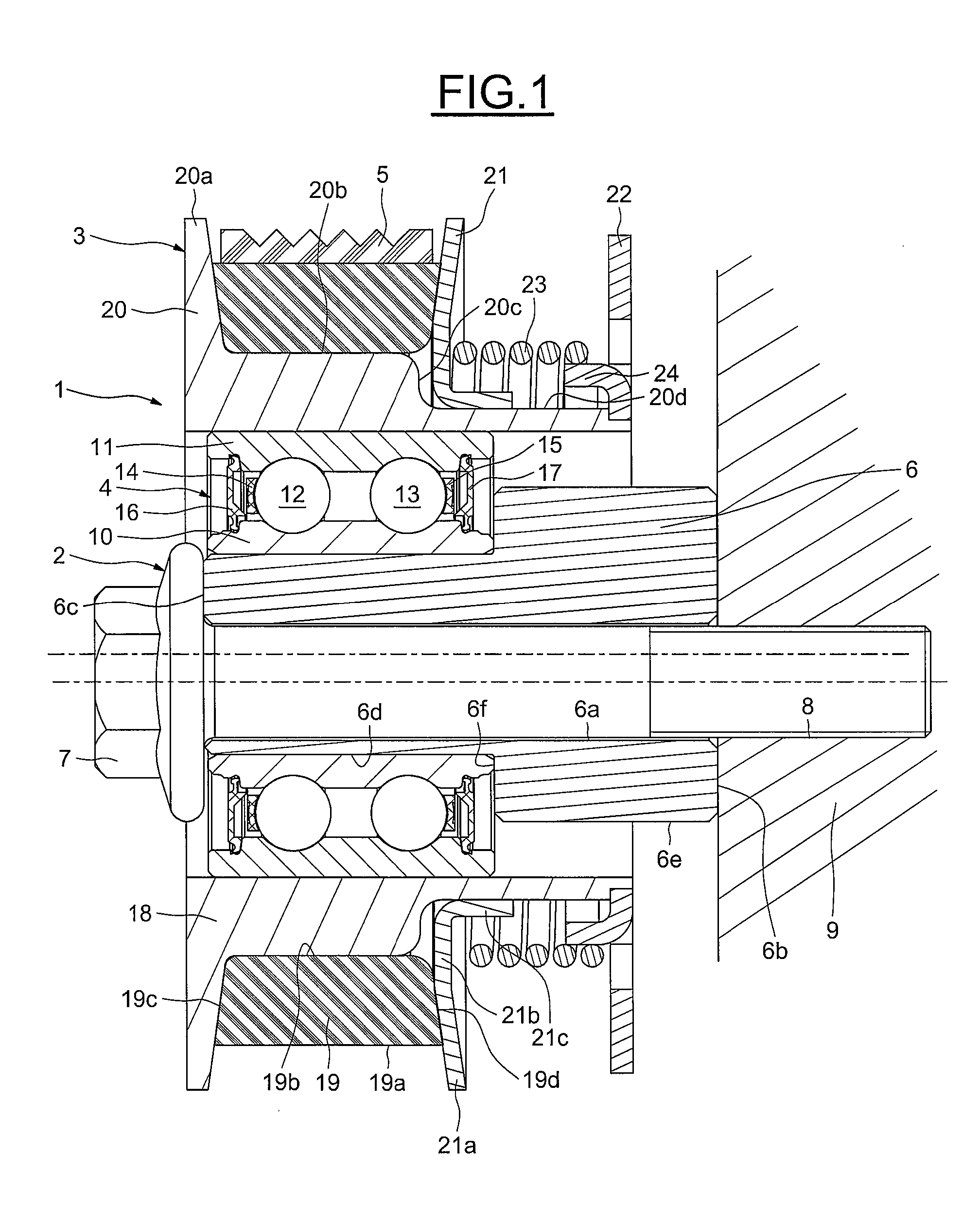
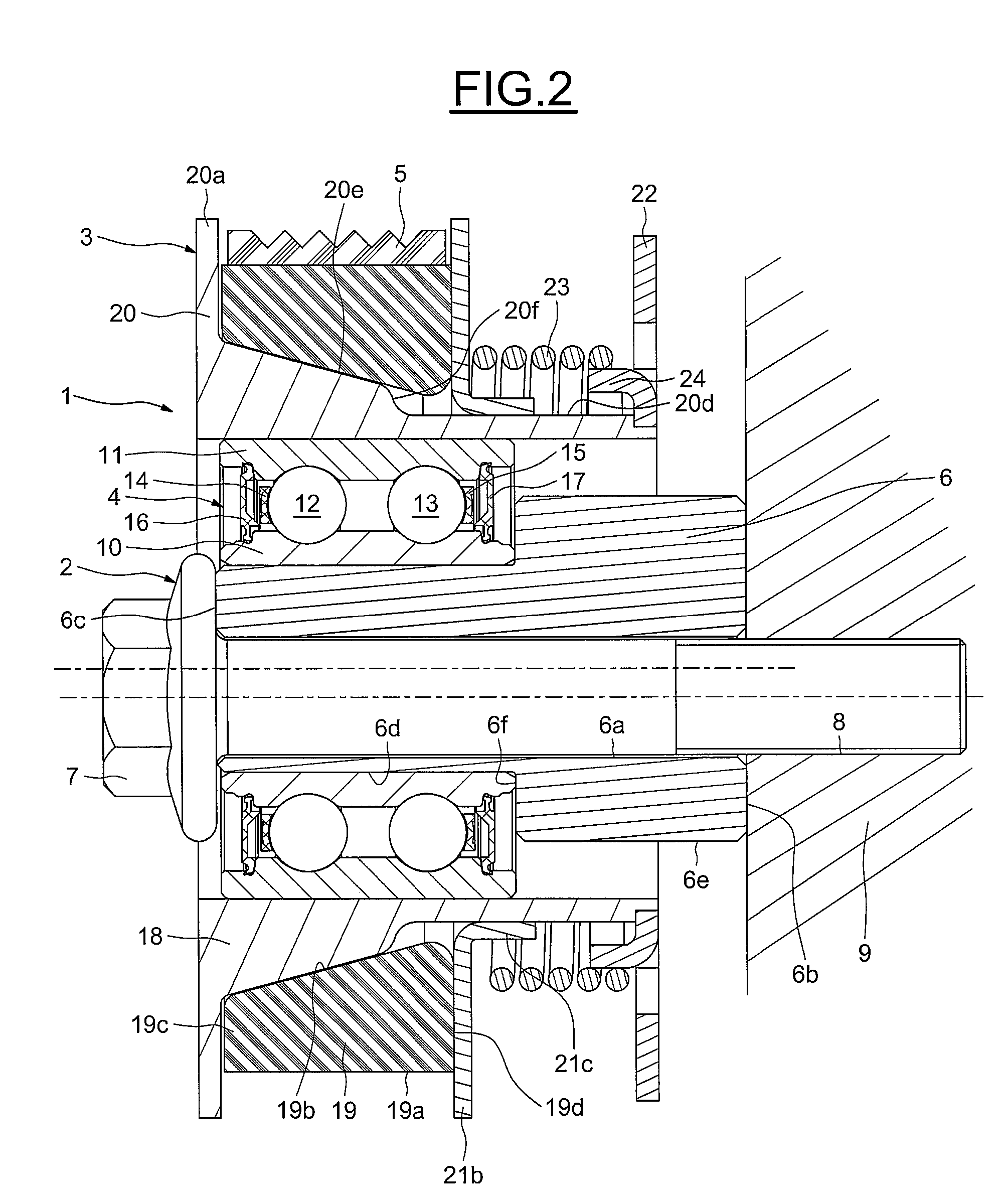
[0009]The tensioning roller device includes a non-rotating part about which there is rotationally mounted a pulley-forming rotating assembly designed to collaborate with a belt or a chain and a rolling bearing positioned between the non-rotating part and the pulley and including a rotating ring, a non-rotating ring and rolling elements. The pulley includes a rigid rim including a first part fixed to the rotating ring of the rolling bearing and a second part that can move with respect to the first part under the action of an elastic element, and an expandable sleeve of annular overall shape designed to be in contact with the belt, the diameter of the expandable sleeve varying according to how hard it is pressed by the second part. The first part can be obtained economically by casting or machining a light alloy, alternatively by machining a steel blank. The second part can be formed by pressing a sheet, and this proves particularly economical. The expanding sleeve can be obtained by molding a flexible material, for example a natural and / or synthetic elastomer, possibly containing a filler, for example a filler in fiber or powder form that allows its mechanical properties to be adjusted.
[0029]This then yields an automatic tensioning roller device of a reasonable mass, which is compact, is made up of component parts, the shapes of which are relatively simple and economical, both to manufacture and to assemble. Because the sleeve in contact with the belt is of annular shape, the amount of vibration generated is extremely small.

Problems solved by technology

While such devices are satisfactory from the performance standpoint, their very high number of component parts is a disadvantage, and they are generally expensive to manufacture.
However, this type of pulley is heavy, wears quickly, carries a risk of vibration and noise, and is expensive, as much because of the number of component parts as because of their complexity, which parts need to be fitted together particularly accurately.
Manufacturing and assembling the blocks are expensive.
There is a risk that the conical component will become skewed, causing the pulley to become unbalanced and generating vibrations.
Furthermore, the discontinuous contact between the blocks and the belt also causes vibrations and variations in the belt tension, which are likely to result in premature wear.

Method used


Image

  • Tensioning roller device
  • Tensioning roller device
  • Tensioning roller device

Examples


Embodiment Construction

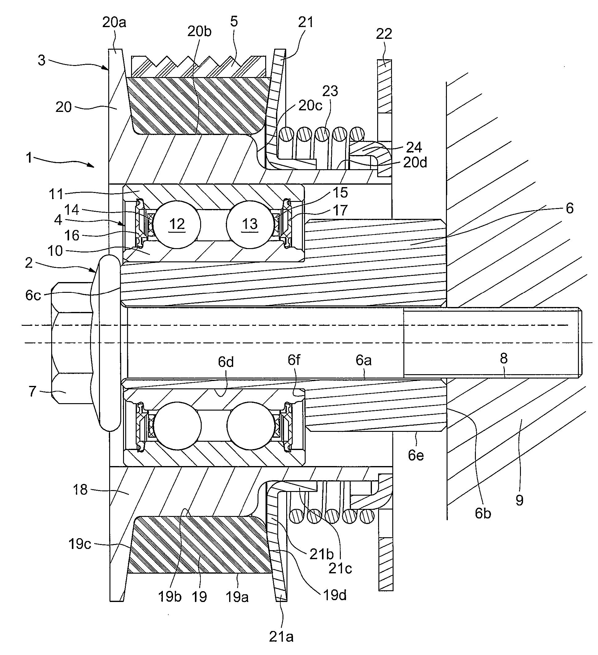
[0034]As can be seen in FIG. 1, the tensioning roller device, referenced 1 in its entirety, includes a stationary part 2 and a rotating part 3 mounted to rotate with respect to the fixed part 2 by means of a rolling bearing 4. The rotating part 3 is designed to be in contact with a belt or the chain 5 in order to tension the belt or chain 5.

[0035]The fixed part 2 includes an adjustment eccentric 6 and a screw 7 positioned in a bore 6a of the adjustment eccentric 6. One end of the screw is engaged in a threaded hole 8 formed in a support 9, for example an engine block. The adjustment eccentric 6 is in contact via one radial face with the support 9 and via an opposite radial face with the head of the screw 7. The adjustment eccentric 6 has an exterior surface of revolution which is stepped with a large-diameter portion on the same side as the support 9 and a small-diameter portion on the same side as the head of the screw 7, the rolling bearing 4 being pushed onto the small-diameter p...


PUM


Abstract

Tensioning roller device including a non-rotating part about which there is rotationally mounted a pulley-forming rotating assembly designed to collaborate with a belt or a chain and a rolling bearing positioned between the non-rotating part and the pulley and including a rotating ring, a non-rotating ring and rolling elements, the pulley including a rigid rim including a first part fixed to the rotating ring of the bearing and a second part that can move with respect to the first part under the action of an elastic element, and an expandable sleeve of annular overall shape designed to be in contact with the belt or the chain, the diameter of the expandable sleeve varying according to how hard it is pressed by the second part.

Description

BACKGROUND OF THE INVENTION[0001]1. Field of the Invention[0002]The present invention generally relates to the field of belt or chain tensioning roller devices, particularly automatic tensioning rollers, used in particular to ensure appropriate belt or chain tension, for example in timing belts or belts used to drive auxiliaries or the like. Automatic tensioning rollers such as these can be used in motor vehicle combustion engines and allow the belt tension to be kept always within a predetermined range.[0003]2. Description of the Relevant Art[0004]Tensioning rollers generally include a support intended to be fixed to an engine block, and a moving part that can move angularly with respect to the support. The moving part is provided with an eccentric and with a rolling bearing on which there is mounted a roller intended to be in contact with the belt. A spring constantly exerts a tensioning force between the support and the moving part, causing the roller to be in contact with the be...

Claims


Application Information

Patent Timeline
IPC IPC(8): F16H7/08
CPCF16H7/08F16H55/54F16C13/006F16H2007/0872F16H2007/0889F16H2007/0806F16C19/08F16C2361/63
Inventor GABOREL, JEAN-PHILIPPENWOKOYE, DONATUSLESCORAIL, ROMUALDVARNOUX, LAURENT
Owner AB SKF
Learn More