Short wire stent delivery system with splittable outer sheath

a delivery system and split-type technology, applied in the field of short-wire stent delivery systems with split-type outer sheaths, can solve the problems of further slowed process, existing devices that do not offer the ability to place a second wire guide after the first one, etc., and achieve the effect of eliminating friction and greatly facilitating the removal of the delivery system

Inactive Publication Date: 2008-07-10
COOK INC
View PDF7 Cites 102 Cited by
  • Summary
  • Abstract
  • Description
  • Claims
  • Application Information

AI Technical Summary

Benefits of technology

[0013]Once the prosthesis has been deployed and the guiding member has been separated from the inner and outer members, then the delivery system can be retracted and removed from the patient without dislodging or disrupting the position or placement of the guiding member. Removal of the delivery system is greatly facilitated by the elimination of friction which would have otherwise existed betwee...

Problems solved by technology

Nevertheless, these techniques still require that a short exchange procedure be performed outside the patient, and care must be taken to prevent loss of wire guide access to the duct during the exchange procedure.
Moreover, the process is further slowed by the frictional resistance between the wire guide and catheter, which remains a problem in subsequent exchanges as devic...

Method used


Image

  • Short wire stent delivery system with splittable outer sheath
  • Short wire stent delivery system with splittable outer sheath
  • Short wire stent delivery system with splittable outer sheath

Examples


Embodiment Construction

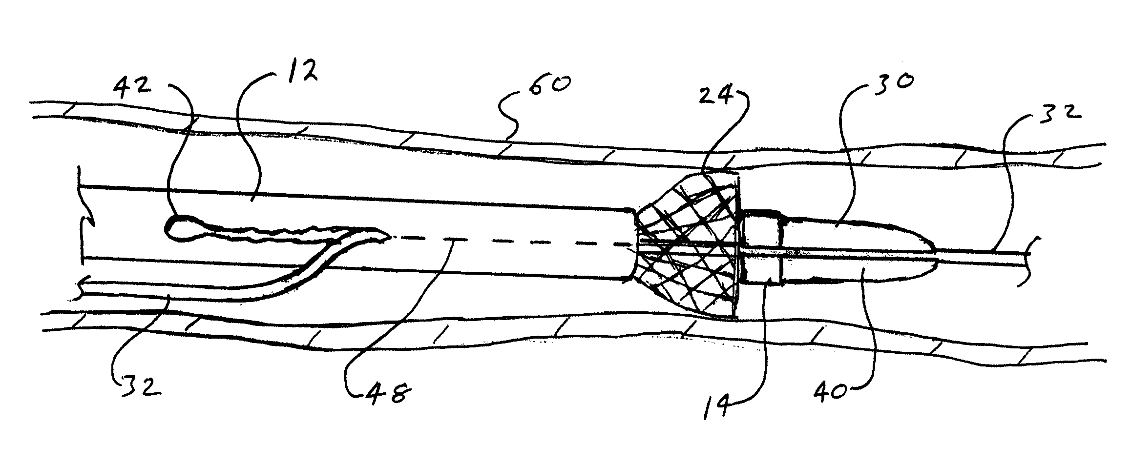
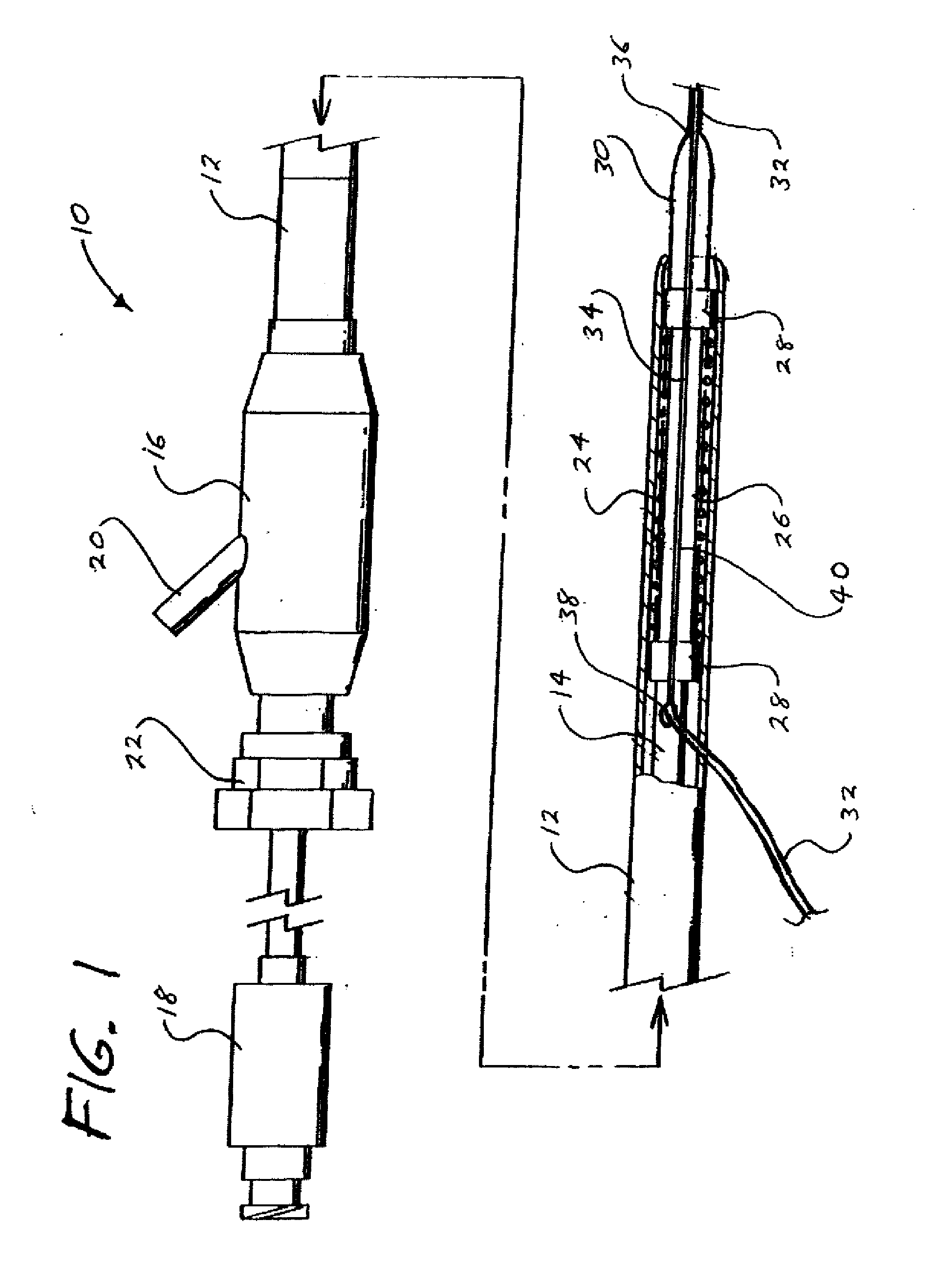
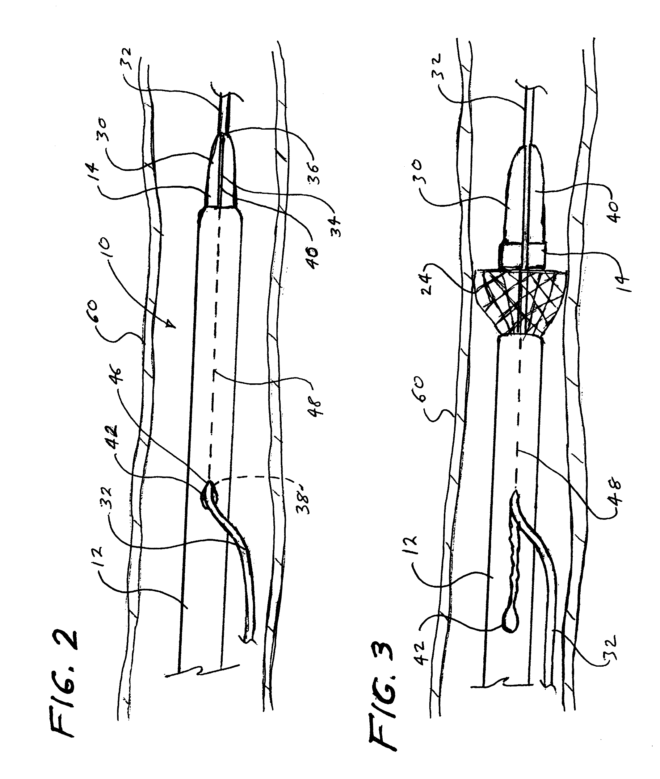
[0024]An exemplary prosthesis delivery system and method for introducing an expandable prosthesis over an indwelling guiding member, such as a wire guide, into a patient by remotely uncoupling the delivery system from the guiding member within the work site (defined as a lumen, duct, organ, vessel, other bodily passage or cavity, or the pathway leading thereto in which wire guide / guiding member access is maintained throughout a particular procedure or series of procedures), thereby facilitating the removal of the delivery system and simplifying introduction of a secondary access device or delivery system over the indwelling wire without an exchange of devices taking place outside of the patient is shown in the embodiments illustrated in FIGS. 1-12.

[0025]A first exemplary embodiment of the delivery system 10 is depicted in FIGS. 1-8a, which comprises an elongate outer member 12 that is slidably disposed about an elongate inner member 14. The elongate outer member 12 is commonly ref...


PUM


Abstract

A delivery system and method for introducing a self-expanding prosthesis into a work site of a patient. The delivery system is introduced to the work site over an elongate guiding member. The delivery system is subsequently uncoupled from the guiding member upon deployment of the prosthesis while remaining within the work site. In an exemplary embodiment of the invention, the delivery system comprises an elongate outer member slidably disposed about an elongate inner member. A self-expanding prosthesis is disposed within the outer member and is laterally constrained thereby in a compressed delivery configuration, and is constrained against longitudinal movement relative to the inner member. The inner member further comprises a passageway extending through the distal portion thereof the passageway extending between a distal opening near the distal end of the inner member and a proximal opening spaced proximally from the distal end of the inner member. The outer member comprises an opening in communication with the proximal opening of the inner member. The inner and outer members are configured to allow a guiding member disposed through the passageway and openings to pass laterally out of the passageway and openings upon proximal movement of the outer member relative to the inner member and deployment of the prosthesis.

Description

CROSS-REFERENCE TO RELATED APPLICATIONS[0001]This application claims the benefit of U.S. Provisional Application Ser. No. 60 / 879,709, filed Jan. 10, 2007, entitled “Short Wire Stent Delivery System With Splittable Outer Sheath”, the entire contents of which are incorporated by reference.TECHNICAL FIELD[0002]The present invention relates to an apparatus for delivering an implantable prosthesis and, in particular, to an apparatus for introducing a self-expanding stent to a desired location within a bodily duct of a patient.BACKGROUND OF THE INVENTION[0003]Self-expanding prosthesis, such as stents, artificial valves, distal protection devices, occluders, filters, etc., are used for a variety of applications. For example, self-expanding stents are used within the vascular and biliary tree to open strictures and maintain the patency of the vessel or duct. Current prosthesis delivery systems generally include an introducer catheter with a self-expanding prosthesis (e.g., a self-expanding ...

Claims


Application Information

Patent Timeline
IPC IPC(8): A61F2/84
CPCA61F2/97A61F2/95
Inventor AGNEW, CHARLES W.
Owner COOK INC
Why Eureka
Try Eureka