
Assistant connector for a tool

a technology of assistant connectors and tools, applied in the direction of yielding couplings, wrenches, screwdrivers, etc., can solve the problems of inability to work, different inconveniences in use, and inability to apply straight-pole operation modes, etc., to achieve durable positioning effect of positioning sleeves, reduce machining costs, and improve convenience and practicability. use

Inactive Publication Date: 2008-07-17
HUNG YU TOOL IND
View PDF3 Cites 8 Cited by
  • Summary
  • Abstract
  • Description
  • Claims
  • Application Information

AI Technical Summary

Benefits of technology

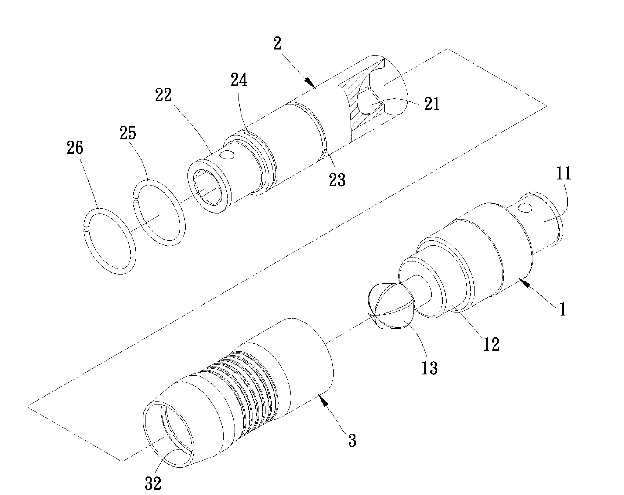
[0017]The primary objective of the present invention is that the pivot head of the connecting member is inserted in the pivot groove of the transmission member, then that holding the positioning sleeve can serve as a firm support in use. Consequently, no matter in the straight-pole mode or in the rotary operational mode, the transmission member can be smoothly driven to rotate by the connecting member equally, and the positioning sleeve is positioned by engaging the two positioning grooves with the C-shaped ring of the transmission member, as a result, preventing returning to the straight-pole operational mode casually when in the rotary operational mode. Consequently, the convenience and the practicability of use are improved.
[0018]The second objective of the present invention is that no special machining is needed, machining cost is relatively low and the positioning effect of the positioning sleeve is durable.
[0019]The third objective of the present invention is that the structure strength is fine, no deformation is likely to occur and it can be applied to a hand tool, an electric tool and a pneumatic tool at the same time. So its applicability is quite fine.

Problems solved by technology

Conventional screwdrivers are all in straight-pole operational mode, however in some special working spaces, the straight-pole operational mode cannot be applied, or even a problem causing unable to work will be derived.
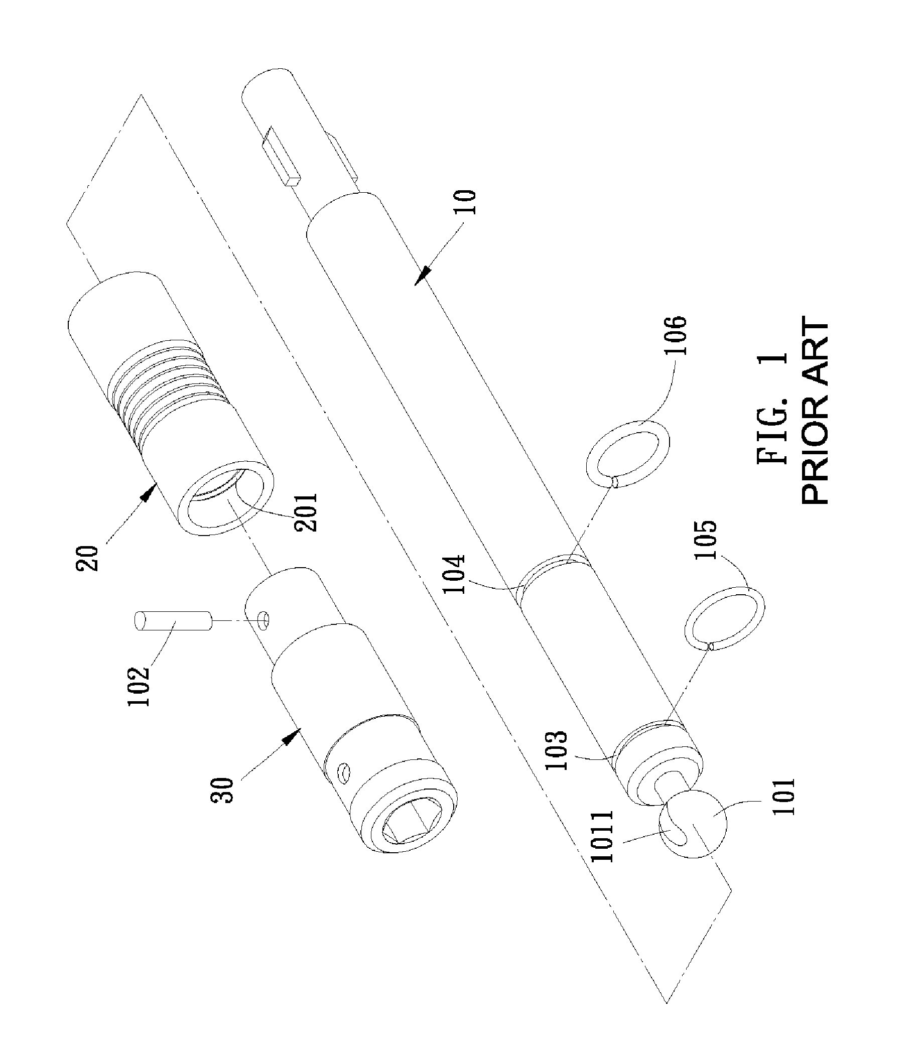
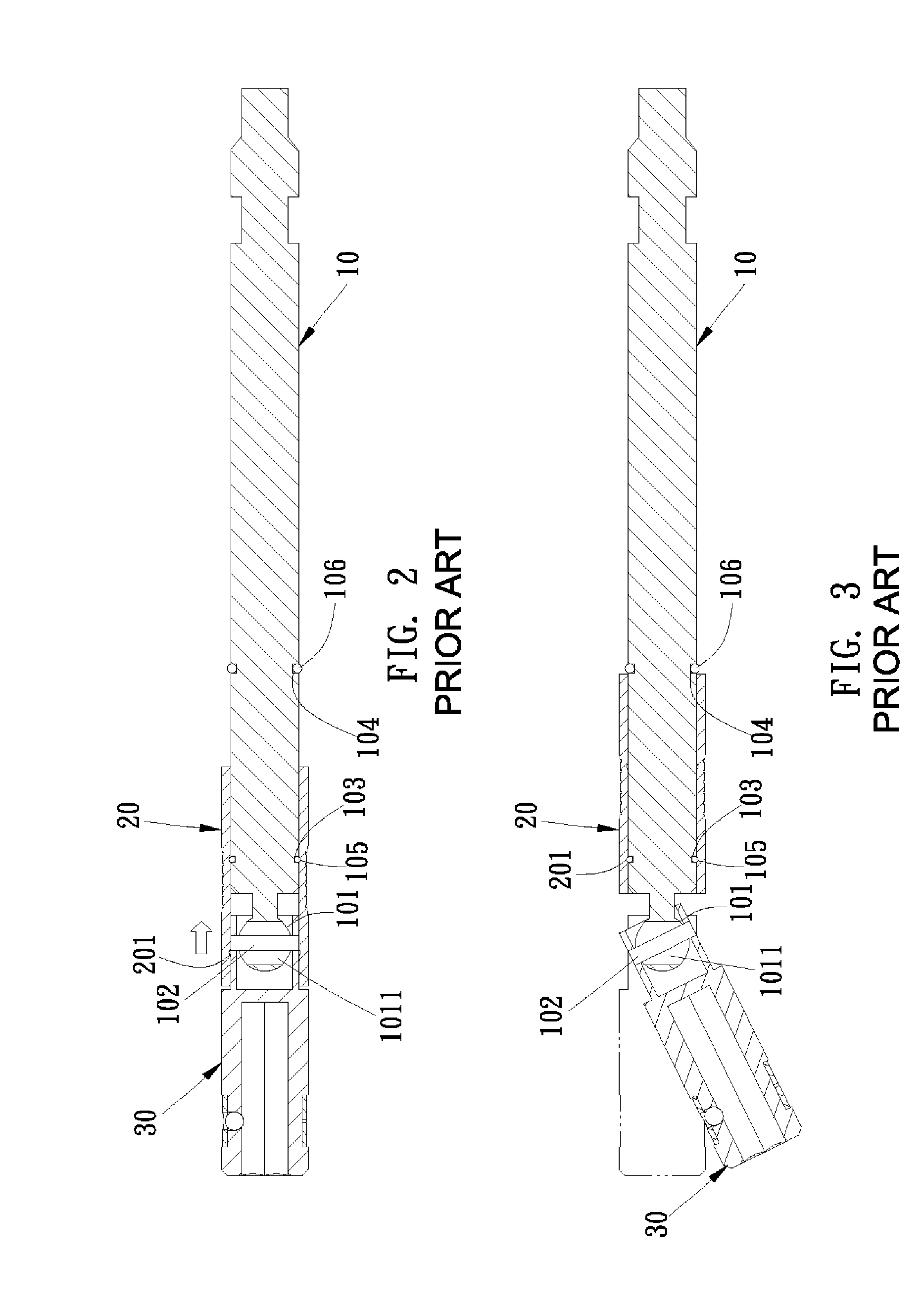
1. The front end of the connecting rod 10 formed with the spherical head 101 defined with the pivot hole 1011 is pivotally coupled to the engaging member 30 by the pin 102, even so the engaging member can freely sway, but the connection relationship between the spherical head 101 and the engaging member 30 will result in that the engaging member 30 cannot be smoothly rotated by the connecting rod 10 and that the engaging member 30 will rotate with the connecting rod 10 in use, so that the engaging member 30 cannot be designed with a holding portion. Consequently, some different inconveniences will occur in use.
2. The pivot hole 1011 flared toward both ends thereof needs to be formed in the spherical head 101 of the front end of the connecting rod 10. The pivot hole is hard to machining because of its special shape, and consequently the machining cost is relatively high.
3. The torque force of the connecting rod 10 for rotating the engaging member 30 is focused on the spherical head 101 and the pin 102. Consequently, if the diameter of the pin 102 is too small, the pin 102 is likely to rupture; if the diameter of the pin 102 is too large, the pivot hole 1011 of the spherical head 101 will correspondingly be larger, thus reducing the structural strength of the spherical head 101, and consequently, the spherical head 101 is likely to be deformed in use.
Consequently, it will return to the straight-pole mode accidentally, causing inconvenience of use.

Method used


Image

  • Assistant connector for a tool
  • Assistant connector for a tool
  • Assistant connector for a tool

Examples


Embodiment Construction

[0033]The present invention will be clearer from the following description when viewed together with the accompanying drawings, which show, for purpose of illustrations only, the preferred embodiment in accordance with the present invention.

[0034]Referring to FIGS. 7-9, an assistant connector for a tool of the preferred embodiment in accordance with the present invention comprises a connecting member 1, a transmission member 2 and a positioning sleeve 3. One end of the connecting member 1 is provided with a first engaging sleeve 11, and the other end of the connecting member 1 is provided with an engaging section 12 and a hexagonal spherical pivot head 13 extending from the engaging section 12. One end of the transmission member 2 is formed with a hexagonal spherical pivot groove 21, and the other end of the transmission member 2 is formed with a second engaging sleeve 22. A first annular groove 23 and a second annular groove 24 are formed at predetermined positions on the outer sur...


PUM


Abstract

An assistant connector for a tool comprises a connecting member, a transmission member and a positioning sleeve. The connecting member is provided with a first engaging sleeve on one end thereof, an engaging section on the other end thereof and a pivot head extending from the engaging section. The pivot head is inserted in one end of a pivot groove of the transmission member provided with a second engaging sleeve on the other end thereof, for forming a freely rotary relationship. In the periphery of the transmission member are formed with a first and a second annular grooves for engaging with a C-shaped ring, respectively. The positioning sleeve formed with a first and a second annular positioning grooves in the inner surface thereof mounts on the transmission member. Thereby, it can meet the requirements of a straight-pole operational mode and a rotary operational mode, achieving simple and convenient operation.

Description

BACKGROUND OF THE INVENTION[0001]1. Field of the Invention[0002]The present invention relates to a tool assistant instrument, and more particularly to an assistant connector for a tool capable of being transformed into a straight-pole mode or a rotary mode according to use requirements.[0003]2. Description of the Prior Art[0004]Conventional screwdrivers are all in straight-pole operational mode, however in some special working spaces, the straight-pole operational mode cannot be applied, or even a problem causing unable to work will be derived. It is the shortcoming of the conventional tools to be improved.[0005]In order to meet the operational requirements in special working spaces, a rotatable assistant connector (as shown in FIGS. 1-3) has been developed, namely a conventional assistant connector for a tool, which comprises a positioning sleeve 20 mounted on a tool connecting rod 10, the front end of the tool connecting rod 10 provided with a spherical head 101 formed with a pivo...

Claims


Application Information

Patent Timeline
IPC IPC(8): F16D3/16F16D3/18F16D3/20B25B23/00
CPCB25B23/0028F16D3/20F16D3/18F16D1/101
Inventor YANG, MIN-LI
Owner HUNG YU TOOL IND
Learn More