
Small animal restraining device with non-traumatic animal loading device

a technology of restraining device and small animal, which is applied in the field of small animal restraining device with non-traumatic animal loading device, can solve the problems of limiting measurement, limiting the range of motion of current restraint tube, and difficulty in conducting tests on un-anesthetized subjects, so as to reduce the area of the tail

Inactive Publication Date: 2008-07-17
STARR LIFE SCI
View PDF48 Cites 35 Cited by
  • Summary
  • Abstract
  • Description
  • Claims
  • Application Information

AI Technical Summary

Benefits of technology

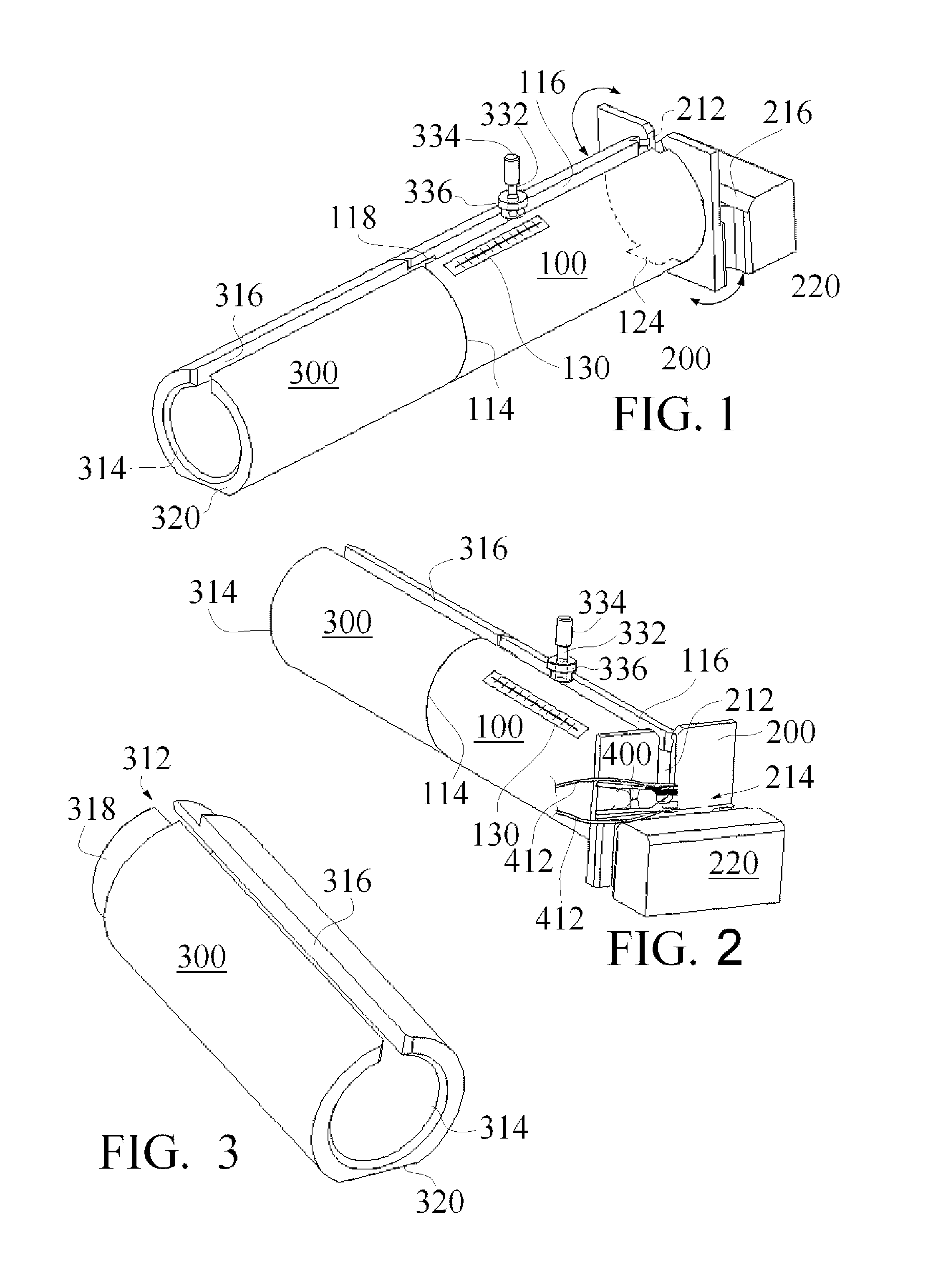
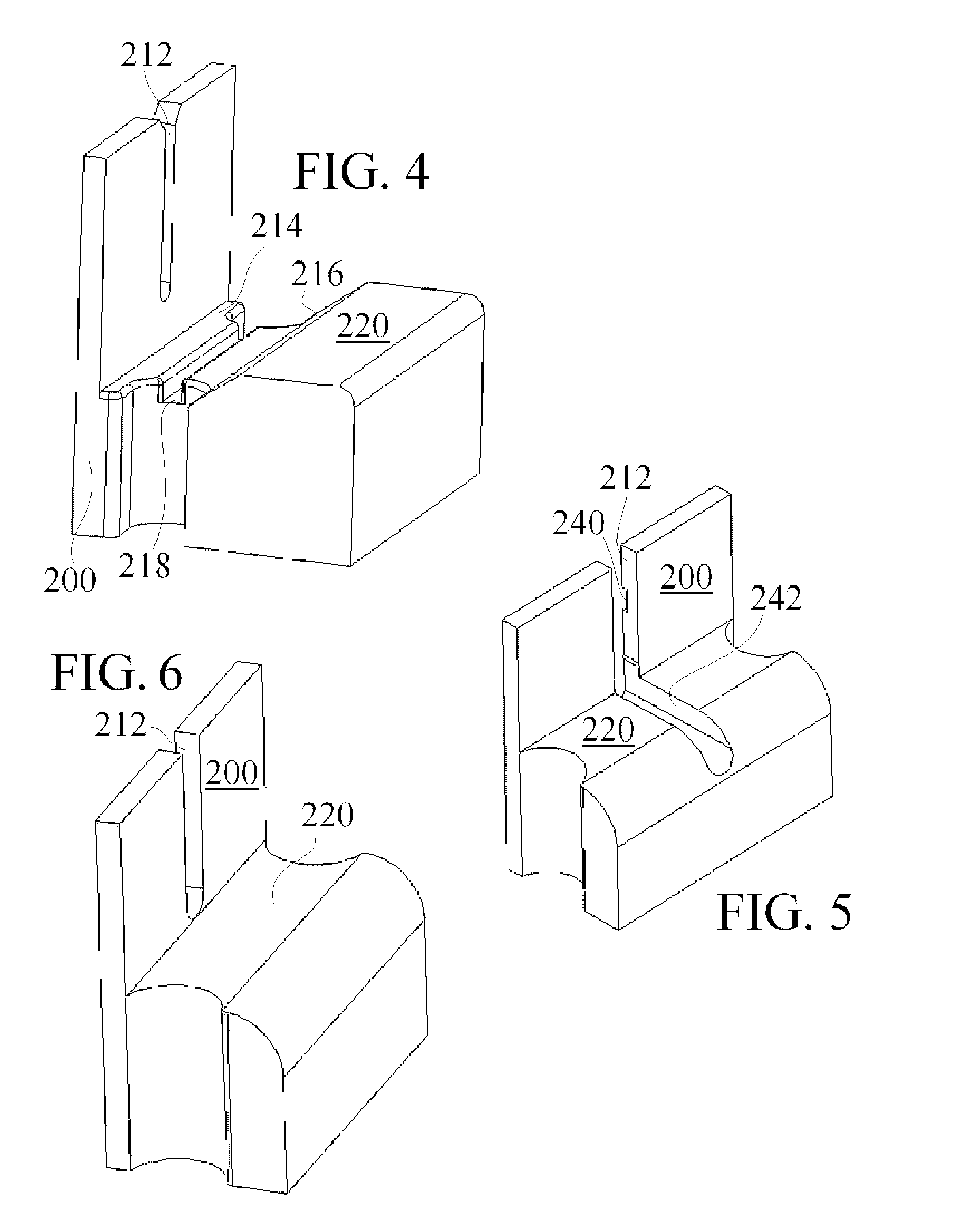
[0020]The physiologic sensor mount may be a tail clip for pulse oximetry sensors. The small animal restraining tube may further include a cable receiving member coupled to the end plate wherein the cable receiving member is configured to receive a cable extending from the physiologic sensors received within the physiologic sensor mount. The small animal restraining tube may further include an aperture reducing plate selectively coupled to the end plate to reduce the area of the tail receiving opening through the end plate.

Problems solved by technology

The primary difficulty associated with conducting tests on un-anesthetized subjects is their mobility.
One drawback with conventional restraining tubes is that current restraint tubes are designed primarily for immobilization only.
The restraining devices often restrict the measurements that can be taken due to limited access to the subject.
A further drawback is that loading of animals into restraining tubes can be traumatic for the animal with the associated physiologic changes to the animal from such stress which can delay the desired research.

Method used


Image

  • Small animal restraining device with non-traumatic animal loading device
  • Small animal restraining device with non-traumatic animal loading device
  • Small animal restraining device with non-traumatic animal loading device

Examples


Embodiment Construction

[0045]The detailed advantages of the present invention will be described further below under separate headings. A summary overview of the invention in connection with the attached figures may be helpful.

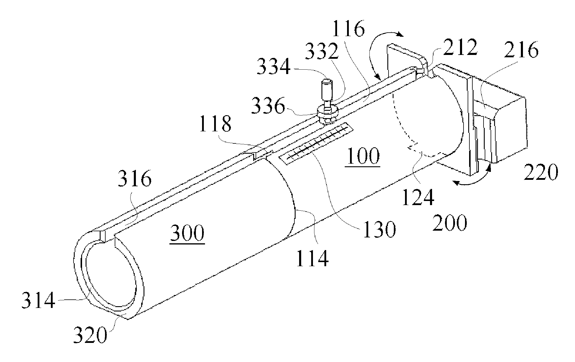
[0046]The invention provides a small animal restraining tube 100 with physiologic sensor mount 214 (which may include a tail clip 400) includes a tube 100 configured to receive a small animal therein. The tube 100 may be take any number of forms such as circular in cross section (interior and exterior), rectangular, oval, a truncated side, or any desired shape. Many suitable materials can be used, but it is advantageous if transparent materials are used to allow for viewing of the animals. Molded acrylics and other polymers have proven cost effective and provide for MRI compatibility.

[0047]A nosecone 330 is within the tube 100 and selectively coupled thereto and configured to abut the animal within the tube 100 to confine the animal on one side of the tube 100. The nosecone can be fo...


PUM


Abstract

A small animal restraining tube comprises a tube configured to receive a small animal therein; a nosecone within the tube and coupled thereto and configured to abut the animal within the tube to confine the animal on one side of the tube; an endplate coupled to the tube and configured to confine a body portion of the animal on a side opposite the nosecone, whereby the body of the animal is confined within the tube between the nosecone and the endplate, the endplate including an opening there through configured to receive a tail of the animal when the animal is confined within the tube; and a tubular loader mechanism selectively coupled to the tube, wherein the loader mechanism is configured to selectively receive the animal therein and configured to transfer the animal to the retraining tube.

Description

RELATED APPLICATIONS[0001]This application claims the benefit of U.S. Provisional patent application Ser. No. 60 / 884,421 filed Jan. 11, 2007 entitled “Physiologic Sensor Mount Integral with Small Animal Restraining Device.”[0002]This application claims the benefit of U.S. Provisional patent application Ser. No. 60 / 891,635 filed Feb. 26, 2007 entitled “Physiologic Sensor Mount Integral with Small Animal Restraining Device with Non-Traumatic Animal Loading Device and Stress Level Indicator.”BACKGROUND OF THE INVENTION[0003]1. Field of the Invention[0004]The present invention relates to physiologic sensor mounts for small animals, and more particularly to physiologic sensor mounts associated with small animal restraining devices with non-traumatic animal loading device and stress level indicator.[0005]2. Background Information[0006]Researchers who conduct experiments using rats and mice often require that their research animals be un-anesthetized during the experiment in order to avoid...

Claims


Application Information

Patent Timeline
Patent Type & Authority Applications(United States)
IPC IPC(8): A01K29/00A01K1/06A61D3/00
CPCA61D3/00A01K1/0613
Inventor TRUITT, PATRICK W.HETE, BERNARD F.STARR, ERIC W.
Owner STARR LIFE SCI
Learn More