Solid Electrolytic Capacitor Inspection Device and Inspection Method
- Summary
- Abstract
- Description
- Claims
- Application Information
AI Technical Summary
Benefits of technology
Problems solved by technology
Method used
Image

Examples
second exemplary embodiment
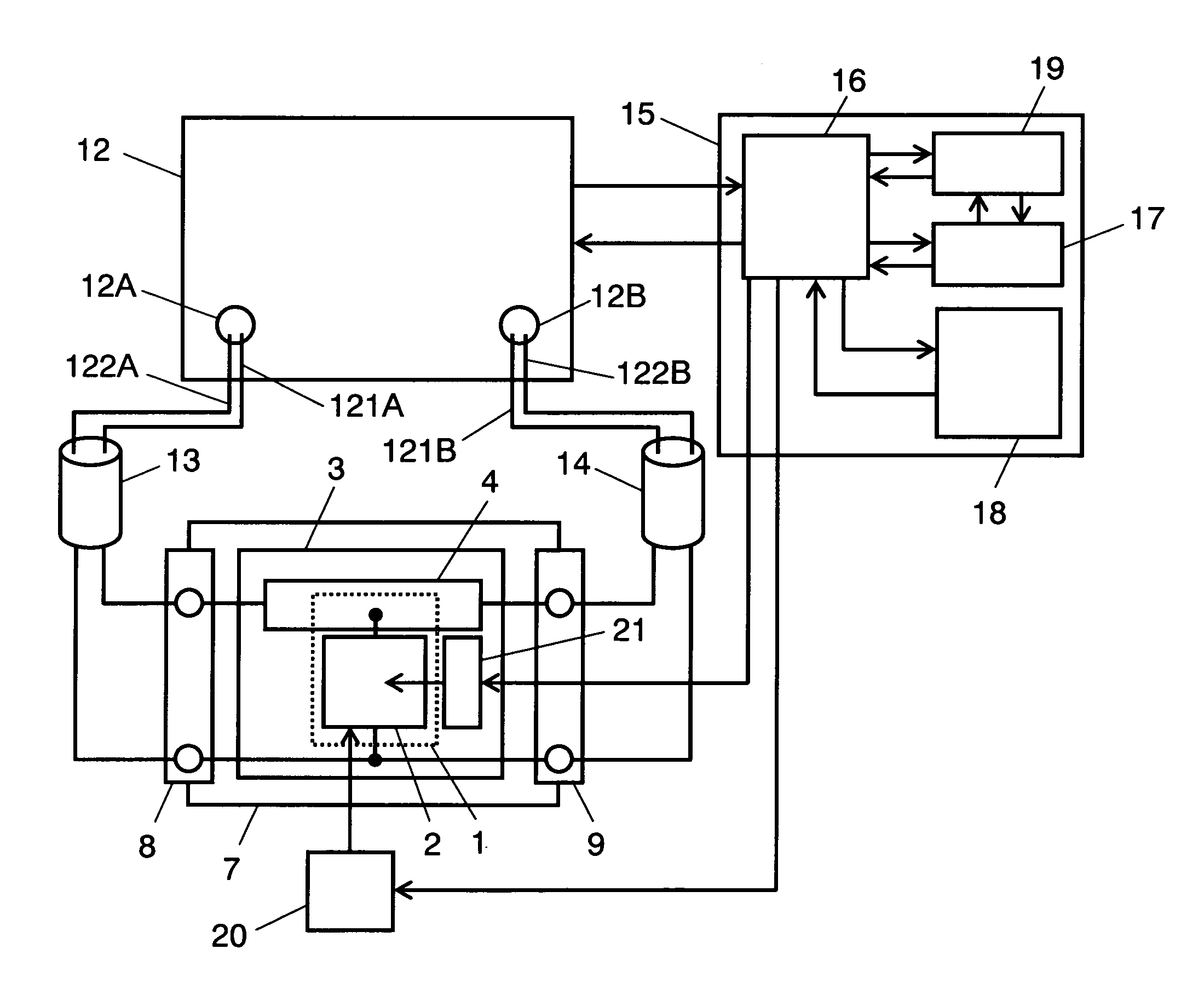
[0102]FIG. 4B is a circuit diagram which shows the connection pattern of capacitor 2, which is an object of inspection, in a measuring method in accordance with a second embodiment of the present invention. The measuring method in the present embodiment is generally called as the series-through method, among the two-port measurement methods.
[0103]In this circuit, capacitor 2 is connected to signal lines 121A and 121B in series in a four-terminal circuit net formed of a combination of signal line 121A and ground line 122A, both of port 12A and signal line 121B and ground line 122B, both of port 12B. Ground line 122A and ground line 122B are connected with each other. Thus, the present embodiment is different from the first embodiment in the connection of capacitor 2, which is the object of inspection. The rest part of the structure remains the same as that of the first exemplary embodiment. However, the arrangement of conductor pattern on substrate 3 and its connection with capacitor...
third exemplary embodiment
[0108]FIG. 4C is a circuit diagram which shows the connection pattern of capacitor 2, which is an object of inspection, in accordance with a third exemplary embodiment of the present invention. The connecting method in the present embodiment is generally called as the reflection type, among the one-port measurement methods.
[0109]In the present circuit, signal line 121A and ground line 122A, both of port 12A, are connected with capacitor 2, respectively. As compared with the first exemplary embodiment, the present embodiment is different in the connection of capacitor 2, which is object of inspection. The rest portion remains the same as that of the first exemplary embodiment. However, the conductor pattern on substrate 3 and the connection of the conductor pattern with capacitor 2 are different from those shown in FIG. 1. These points of difference are described below.
[0110]FIG. 10 shows outline of the connection in a solid electrolytic capacitor inspection device in accordance with...
fourth exemplary embodiment
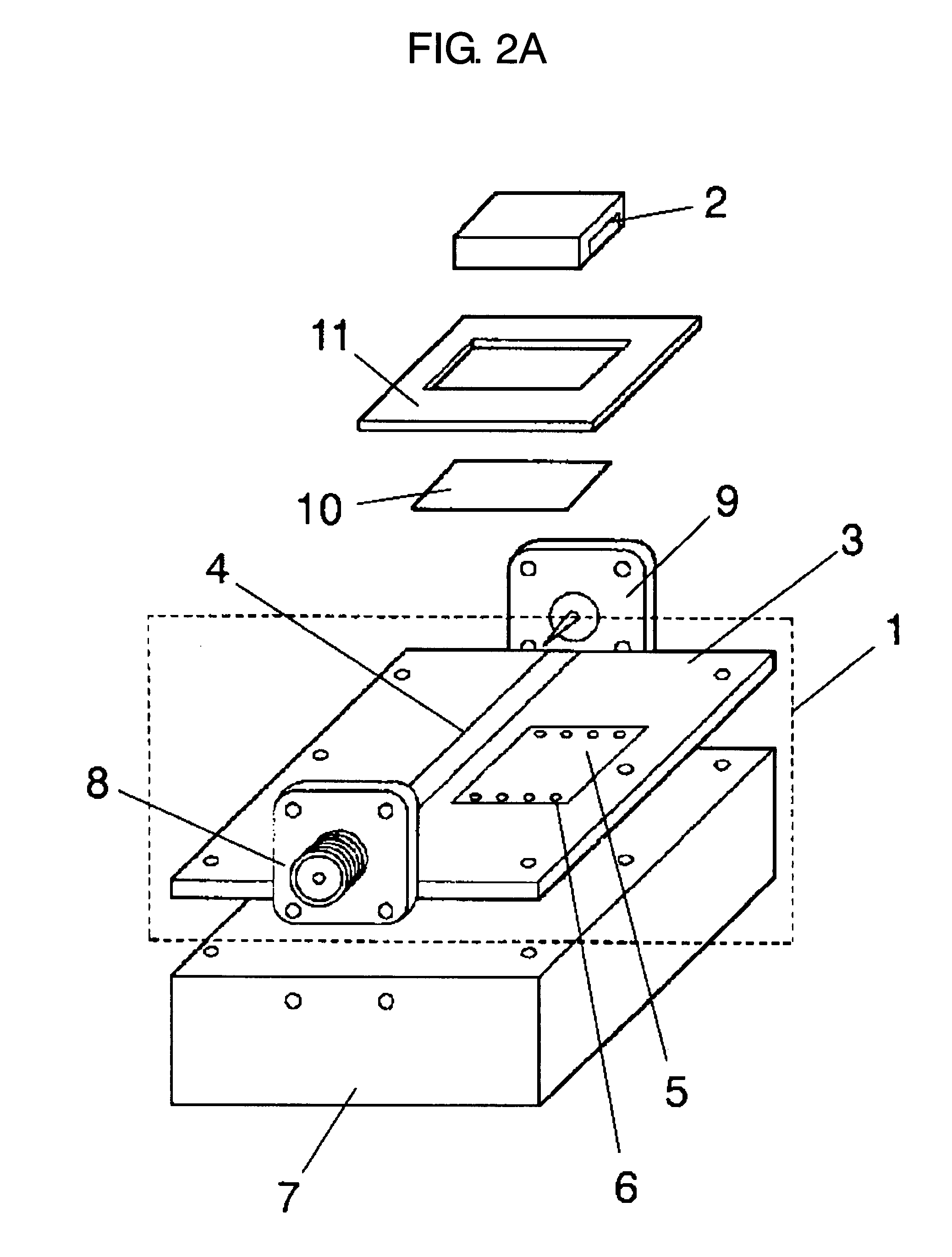
[0112]FIG. 12 is a perspective view showing an appearance of a measuring section of an inspection device in accordance with a fourth exemplary embodiment of the present invention. The point of difference as compared with the first exemplary embodiment is that substrate 3 is provided thereon with first micro strip line 4A and second micro strip line 4B, which function as a first conductor unit, and first cathode electrode 5A and second cathode electrode 5B, which function as a second conductor unit. First micro strip line 4A is connected via connector 8 with input signal line 121A of network analyzer 12 which is shown in FIG. 1. Second micro strip line 4B is connected via connector 9 with output signal line 121B of network analyzer 12. First cathode electrode 5A and second cathode electrode 5B are connected with fixing base 7 via through-hole electrode 6 in the same manner as the cathode electrode in the first embodiment; and connected via connector 8, 9 to ground line 122A at the in...
PUM
 Abstract
Description
Claims
Application Information
 - R&D
- Intellectual Property
- Life Sciences
- Materials
- Tech Scout
- Unparalleled Data Quality
- Higher Quality Content
- 60% Fewer Hallucinations
Browse by: Latest US Patents, China's latest patents, Technical Efficacy Thesaurus, Application Domain, Technology Topic, Popular Technical Reports.
© 2025 PatSnap. All rights reserved.Legal|Privacy policy|Modern Slavery Act Transparency Statement|Sitemap|About US| Contact US: help@patsnap.com