Frequency-Division Circuit

a frequency-division circuit and frequency-division technology, applied in the field of frequency-division circuits, can solve the problems of imposing a high-frequency limit beyond which frequencies are no longer correctly divided, and the speed increase will generally be at the expense of higher power consumption, so as to achieve the effect of reducing power consumption and increasing the frequency limi

Active Publication Date: 2008-07-17
III HLDG 6
View PDF6 Cites 0 Cited by
  • Summary
  • Abstract
  • Description
  • Claims
  • Application Information

AI Technical Summary

Benefits of technology

[0008]The principle of operation is thus that a multi state circuit is from time to time inhibited to switch to the next state. The next state is by definition defined by the cycle of states. Accordingly, there is no evaluation and decision process in order to determine what the next state will be. The inhibiting operation in accordance with the invention can be significantly faster than the prior art evaluation and decision process for a given power consumption. Consequently, the invention allows a higher frequency limit for a given power consumption. Conversely, the invention allows a reduction in power consumption for given frequency.

Problems solved by technology

This evaluation and decision process, which takes a certain time, imposes a high-frequency limit beyond which frequencies are no longer correctly divided.
However, such a speed increase will generally be at the expense of higher power consumption.

Method used


Image

  • Frequency-Division Circuit
  • Frequency-Division Circuit
  • Frequency-Division Circuit

Examples


Embodiment Construction

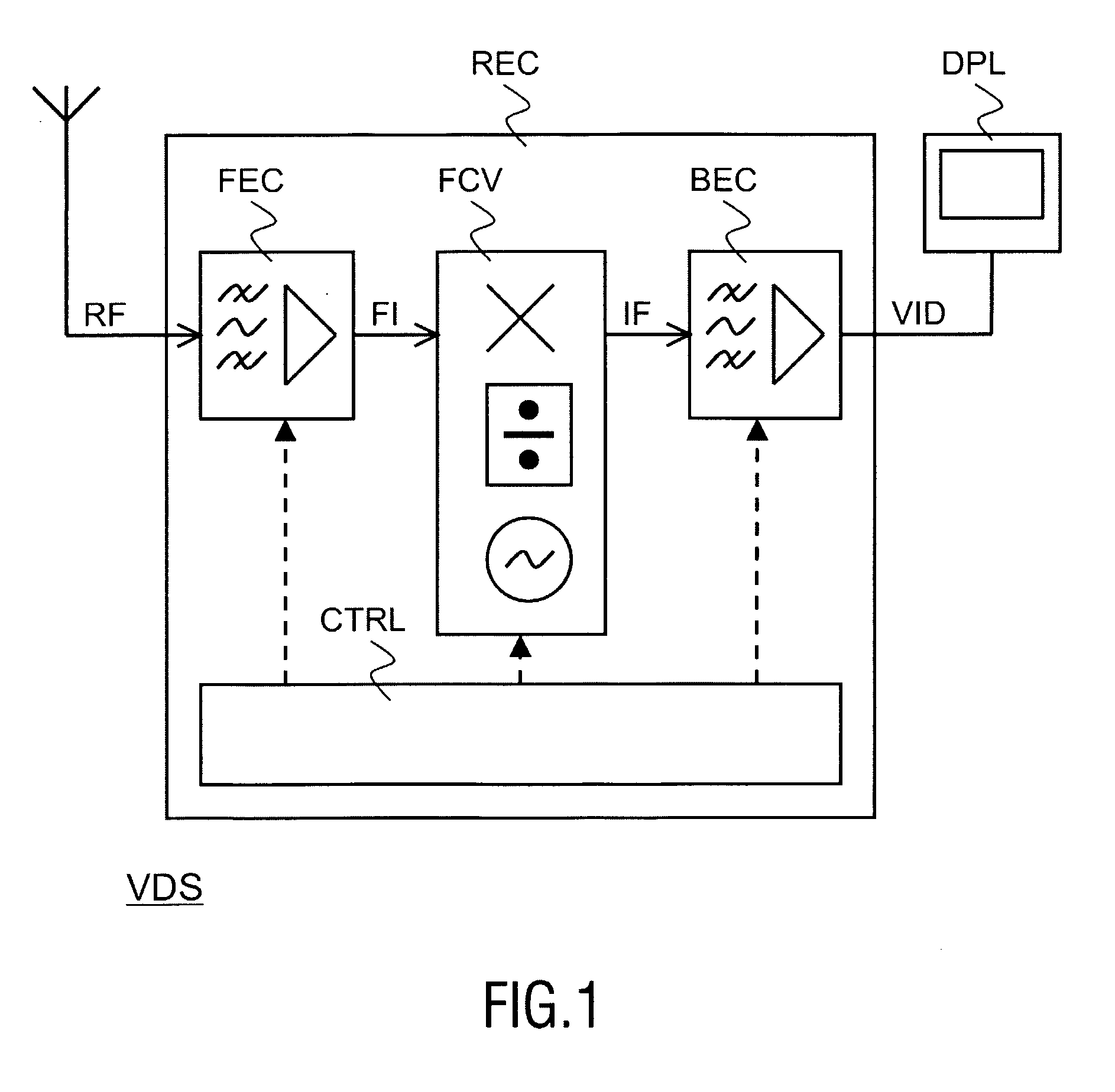
[0027]FIG. 1 illustrates a video display set VDS that comprises a receiver REC and a display device DPL. The receiver REC receives a radiofrequency signal RF and provides in response thereto a video signal VID. The display device DPL displays the video signal VID.

[0028]The receiver REC comprises a front-end circuit FEC, a frequency conversion circuit FCV, a back-end circuit BEC, and a control circuit CTRL. The front-end circuit FEC filters and amplifies the radiofrequency signal RF so as to obtain a frequency-conversion input signal FI. The frequency conversion circuit FCV carries out a frequency conversion so as to obtain an intermediate frequency signal IF. The intermediate frequency signal IF is a frequency-shifted version of the frequency-conversion input signal FI and thus a frequency-shifted version of the radiofrequency signal RF. The back-end circuit BEC selects a certain portion of the frequency spectrum of the intermediate frequency signal IF. The back-end circuit BEC proc...


PUM


Abstract

A frequency-division circuit comprises a pair of multi-state circuits (MSCA, MSCB). Each multi-state circuit can be switched throughout a cycle of states (SA(1), . . . , SA(N); SB(1), . . . , SB(N)). One multi-state circuit (MSCA) switches to a next state in response to a rising edge (Er) in an input signal (OS). The other multi-state circuit (MSCB) switches to a next state in response to a falling edge (Ef) in the input signal (OS). Each multi-state circuit (MSCA, MSCB) has at least one state (SA(1), SB(1)) in which the multi-state circuit inhibits the other multi-state circuit (MSCB, MSCA) so as to prevent the other multi-state circuit from switching to the next state.

Description

FIELD OF THE INVENTION[0001]An aspect of the invention relates to a frequency-division circuit. Other aspects of the invention relate to a method of frequency division and a signal processing arrangement that comprises a frequency-division circuit. The signal processing arrangement may be, for example, a receiver for processing a radiofrequency signal that conveys information in the form of audio, video, or data or any combination of those. Yet another aspect of the invention relates to an information-rendering apparatus that comprises such a signal processing arrangement. The information-rendering apparatus may be, for example, a video display set.BACKGROUND OF THE INVENTION[0002]U.S. Pat. No. 4,866,741 describes a 3 / 2 frequency divider. The frequency divider comprises two D flip-flops. Each D flip-flop has a D input, a clock input, a Q output and a Q-not output. One flip-flop receives an input signal at its clock input, the other flip-flop receives the inverse of the input signal ...

Claims


Application Information

Patent Timeline
Patent Type & Authority Applications(United States)
IPC IPC(8): H03K21/10H03K23/00
CPCH03K29/00H03K23/00
Inventor BREKELMANS, JOHANNES H. A.
Owner III HLDG 6
Why Eureka
Try Eureka