Mixer fabrication technique and system using the same

a technology of mixers and fabrication techniques, applied in the field of frequency mixers, can solve the problems of inability to scale up to high-volume automated assembly, and inability to achieve the bandwidth of hybrid mixers. achieve the effect of high frequency limit, superior bandwidth capability, and superior to hybrid mixers

Inactive Publication Date: 2014-04-10
MARKI MICROWAVE
View PDF3 Cites 7 Cited by
  • Summary
  • Abstract
  • Description
  • Claims
  • Application Information

AI Technical Summary

Benefits of technology

[0008]One advantage of the present invention is that it is well suited for all types of applications, from low to high volume production.
[0009]Another advantage of the present invention is that it offers a high frequency limit that is superior to hybrid mixers, and has superior bandwidth capability. The mixer of the present application is ten times smaller than hybrid mixers operating at comparable frequencies, and has the same approximate weight as monolithic mixers.
[0010]Thus, in accordance with one aspect of the present invention, the above-identified and other advantages are achieved by a method of manufacturing an improved microwave mixer that includes sequentially forming a first metal layer, a substrate, and a second metal layer; patterning the substrate and first and second metal layers to form at least one interconnect that electrically contacts the first and second metal layers; patterning at least two passive circuits on the second metal layer of the substrate; patterning the second metal layer of the substrate to expose one or more portions of the substrate; forming a thin dielectric layer on the patterned second metal layer of the substrate, wherein the thin dielectric layer directly contacts the second metal layer and the exposed substrate; processing the thin dielectric layer to create dielectric vias; forming a top layer metal directly on the thin dielectric layer, wherein the top layer metal is connected to the first and second metal layers of the substrate by the dielectric vias formed in the thin dielectric layer; patterning the top layer metal and a portion of the thin dielectric layer to form the top layer metal of the passive circuits and to expose the substrate; attaching an integrated circuit (IC) to the second metal layer of the substrate, wherein the IC includes at least one combination of non-linear devices, and wherein the IC is directly connected to the passive circuits on the second metal layer of the substrate; and forming a protection layer on the IC.
[0011]In accordance with still another aspect of the present invention, the above-identified and other advantages are achieved by an improved microwave mixer. The microwave mixer includes: a first metal layer; a dielectric substrate on the first metal layer; a second metal layer directly on the substrate, wherein the substrate includes at least one substrate via electrically contacting the first metal layer and the second metal layer; at least two passive circuits arranged on the second metal layer and a top layer metal; a thin dielectric layer on the second metal layer, wherein the thin dielectric layer includes dielectric vias, wherein the top layer metal is directly on the thin dielectric layer and electrically connects the first and second metal layers of the substrate; an integrated circuit (IC) attached to the second metal layer, wherein the IC includes at least one combination of non-linear devices, and wherein the IC is directly connected to the passive circuits on the second metal layer; and a protection layer on the IC.

Problems solved by technology

However, a drawback of hybrid mixers is that they are typically large sized, and their method of manufacture is not easily scalable to high volume automated assembly.
Unfortunately, monolithic mixers are inferior to hybrid mixers in terms of their overall performance and in terms of their circuit sophistication.
More specifically, monolithic mixers cannot achieve the bandwidth of hybrid mixers because the passive circuits of the monolithic mixer, for example, baluns, are too highly coupled to the ground plane.
However, that approach will force the line widths to shrink resulting in higher insertion loss.
For these reasons, it is not practical to make passive monolithic mixers that have bandwidth greater than a few octaves.

Method used


Image

  • Mixer fabrication technique and system using the same
  • Mixer fabrication technique and system using the same
  • Mixer fabrication technique and system using the same

Examples


Embodiment Construction

[0019]It is to be understood that both the foregoing general description and the following detailed description are exemplary. As such, the descriptions herein are not intended to limit the scope of the present invention. Instead, the scope of the present invention is governed by the scope of the appended claims.

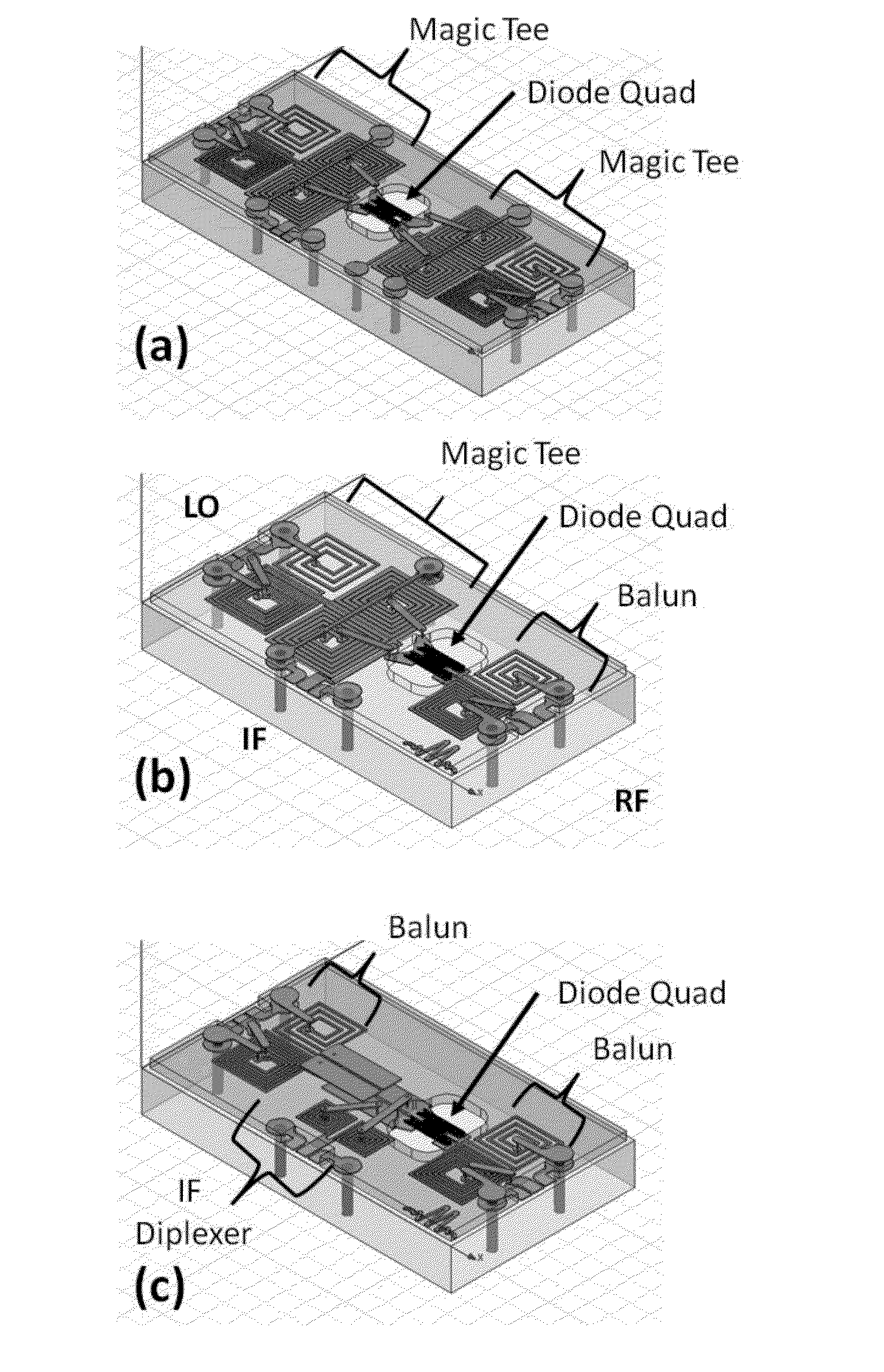
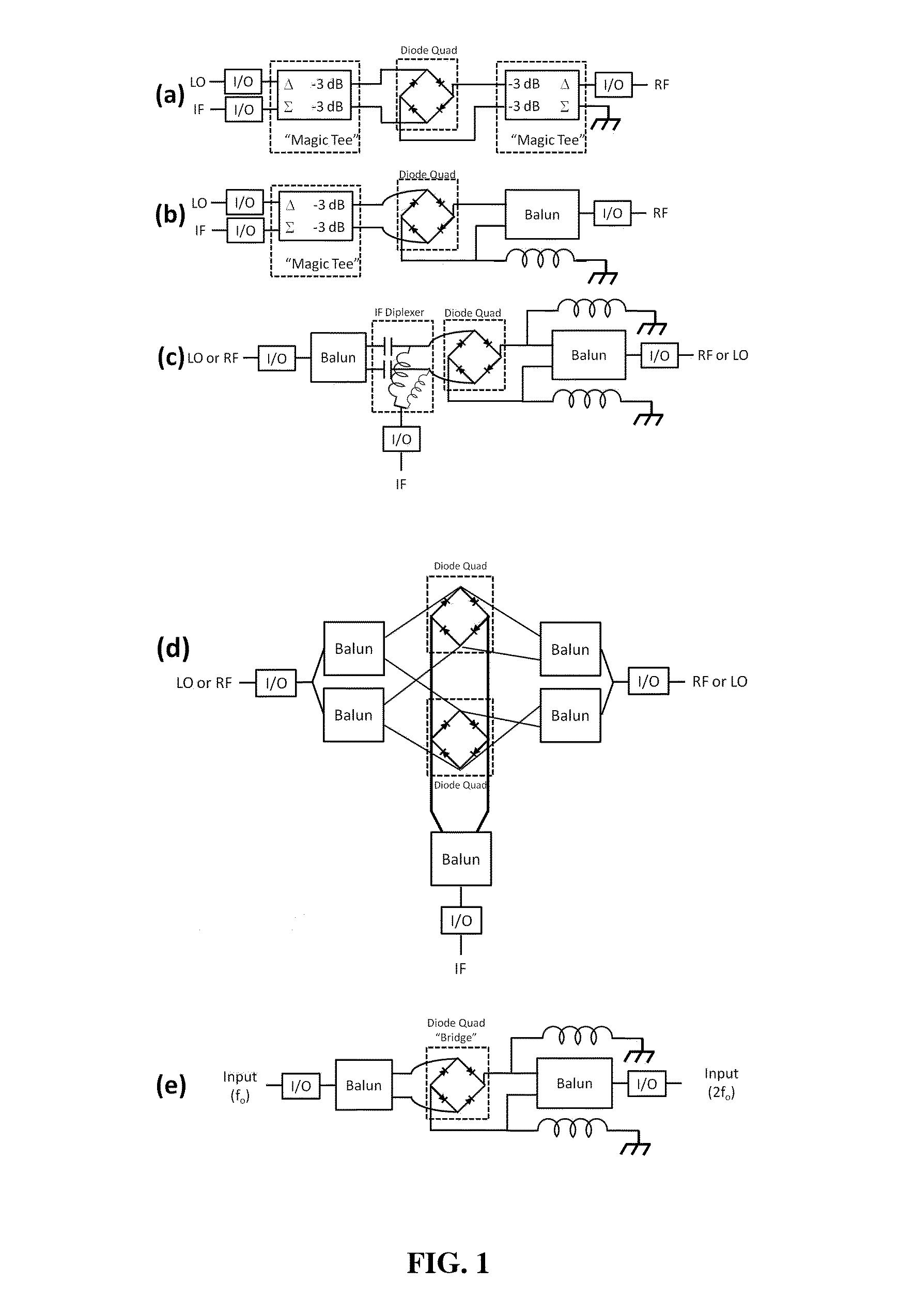
[0020]Balanced mixers, whether hybrid or monolithic, are constructed by connecting integrated circuit (IC) devices, for example, Schottky diodes or field effect transistors (FETs) to surrounding passive circuitry. The surrounding passive circuitry most often consists of various combinations of elements, for example, inductors and capacitors, balanced transmission lines, Magic Tee couplers, and balanced to unbalanced (balun) converters. FIG. 1A illustrates a double balanced mixer circuit with two Magic Tee circuits. FIG. 1B illustrates a double balanced mixer circuit with a Magic Tee circuit on the local oscillator (LO) and intermediate frequency (IF) side and a balun on the ...


PUM

PropertyMeasurementUnit
thicknessaaaaaaaaaa
thicknessaaaaaaaaaa
thicknessaaaaaaaaaa

Abstract

An improved microwave mixer manufactured using multilayer processing includes an integrated circuit that is electrically connected to a top metal layer of a substrate. The microwave mixer includes: a first metal layer; a dielectric substrate on the first metal layer; a second metal layer directly on the substrate, at least two passive circuits arranged on the second metal layer and a top layer metal; a thin dielectric layer on the second metal layer, wherein the top layer metal is directly on the thin dielectric layer; an integrated circuit (IC) attached to the second metal layer, wherein the IC includes at least one combination of non-linear devices, and wherein the IC is directly connected to the passive circuits on the second metal layer; and a protection layer on the IC.

Description

[0001]This application claims priority to U.S. Provisional Application No. 61 / 710,994, filed on Oct. 8, 2012, which is hereby incorporated by reference for all purposes as if fully set forth herein.FIELD OF THE INVENTION[0002]The present invention relates in general to frequency mixers. More specifically, the present invention relates to microwave mixers and methods of manufacturing mixers having a compact design and improved electrical performance.BACKGROUND OF THE INVENTION[0003]Mixers are fundamental building blocks in electronics. A frequency mixer is a 3-port electronic circuit having two input ports and an output port. The mixer multiplies the two incoming electromagnetic signals to output the sum or difference frequency. Radio Frequency (RF) and microwave mixers are commercially available in a large number of styles, packages, and technology platforms ranging from discrete coaxial packages to gallium arsenide (GaAs) integrate circuits (ICs) to fully integrated silicon IC rece...

Claims


Application Information

Patent Timeline
Patent Type & Authority Applications(United States)
IPC IPC(8): H03D7/02H05K3/30
CPCH05K3/30H03D7/02H05K1/0243H05K1/0306H05K1/165H05K3/4605H05K2201/10174H01P5/10H03D7/1408H03D7/1458H03D7/1466H03D2200/0023Y10T29/49128H03H1/00
Inventor MARKI, CHRISTOPHER FERENC
Owner MARKI MICROWAVE
Why Eureka
Try Eureka