Substrate processing apparatus, substrate processing method, and computer-readable storage medium

a substrate processing and processing method technology, applied in the direction of photomechanical equipment, instruments, transportation and packaging, etc., can solve the problems of affecting the uniformity of thermal processes, affecting the suction performance of suction apparatus, and affecting the suction performance of substrates. , to achieve the effect of preventing the substrate from being damaged or broken, enhancing the suction performance of the suction apparatus, and being easy to attra

Active Publication Date: 2008-07-17
TOKYO ELECTRON LTD
View PDF12 Cites 52 Cited by
  • Summary
  • Abstract
  • Description
  • Claims
  • Application Information

AI Technical Summary

Benefits of technology

[0035]In the aspects of the present invention, the substrate is placed on the plural protrusions provided in the heat exchange plate and attracted by suction through the gap regions defined by dividing the gap caused between the substrate and the heat exchange plate using the partition member. The partition member is provided on the heat exchange plate so as to be lower than the plural protrusions, and two dimensionally encl...

Problems solved by technology

However, if the suction performance of, for example, the vacuum pump 107 is strengthened, an excessively large force may be locally applied to the substrate 103, resulting in damage to or breakage of the substrate 103 in some circumstances, as shown in FIG. 2C.
In addition, when more time is needed to straighten the substrate 103, the temperature uniformity of the heat plate 102 may become worse because the heat plate 102 can be cooled unevenly by the nitrogen, which impairs the thermal process that should uniformly heat the substrate 103.
As a result, the suction performance is impaired, so that the substrate 103 may no longer be attracte...

Method used


Image

  • Substrate processing apparatus, substrate processing method, and computer-readable storage medium
  • Substrate processing apparatus, substrate processing method, and computer-readable storage medium
  • Substrate processing apparatus, substrate processing method, and computer-readable storage medium

Examples


first embodiment

[0055]A substrate processing apparatus according to a first embodiment of the present invention is preferably applicable to a coater / developer that spin-coats a film such as a resist film or the like on a substrate, for example, a semiconductor wafer (simply referred to as wafer W, hereinafter) and develops the spin-coated film.

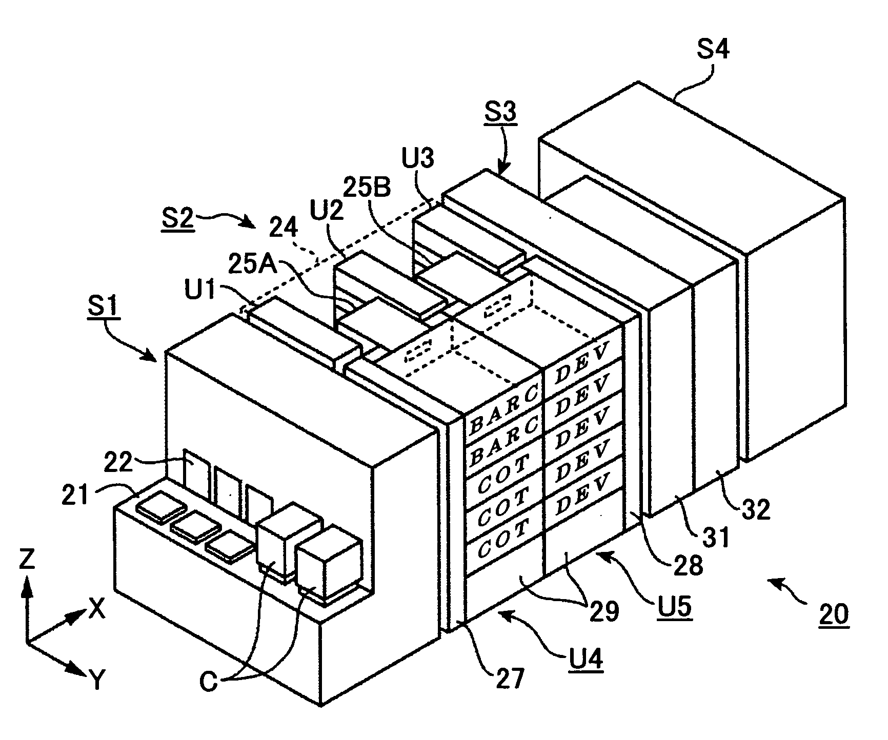
[0056]First, a coater / developer 20 is described in reference to FIGS. 3 and 4. As shown, the coater / developer 20 includes a cassette stage portion Si for transferring wafers W (FIG. 4) in a substrate cassette C. The cassette stage portion S1 has a substrate cassette stage 21 on which plural substrate cassettes C can be placed, doors 22 corresponding to the plural substrate cassettes C placed on the substrate cassette stage 21, and a transfer mechanism 23 that transfers the wafers W from / to the substrate cassettes through the doors 22. By the way, each of the substrate cassettes C can house plural wafers, for example, 13 wafers.

[0057]In addition, the c...

second embodiment

[0084]Next, a substrate processing apparatus according to a second embodiment of the present invention is described in reference to FIG. 9. A substrate processing apparatus 3 according to the second embodiment of the present invention is different from the substrate processing apparatus 2 according to the first embodiment of the present invention in that the thermal plate 61 contains three heaters 64a, 64b, 64c which are connected to corresponding power sources 70a, 70b, 70c. The heaters 64a, 64b, 64c are arranged so as to correspond to the gap regions 80a, 80b, 80c.

[0085]In addition, the substrate processing apparatus 3 includes a control portion 10a having a CPU 13 and a program 12. The program 12 includes a temperature control program 12a that controls outputs from the power sources 70a, 70b, 70c. As already described in reference to FIGS. 8A through 8C, the lowest portion of the wafer W first contacts the protrusions 81; a portion surrounding the contact portion then comes to c...

third embodiment

[0090]Next, a substrate processing apparatus according to a third embodiment of the present invention is described in reference to FIG. 10. Although the suctioned amounts in the gap regions 80a, 80b, 80c are not controlled in the previous embodiments of the present invention, the suctioned amounts are controlled in the substrate processing apparatus according to this embodiment of the present invention.

[0091]As shown in FIG. 10, a substrate processing apparatus 4 according to the fourth embodiment of the present invention includes flow rate controllers 71a, 71b, 71c between the suction apparatus 86 and the valves 85a, 85b, 85c, respectively. The flow rate controllers 71a, 71b, 71c control the amounts of air suctioned from the gap regions 80a, 80b, 80c, respectively, by the suction apparatus 86. By the way, the valves 85a, 85b, 85c and the flow rate controllers 71a, 71b, 71c constitute a flow rate controlling portion 73.

[0092]The substrate processing apparatus 4 includes a controllin...


PUM

PropertyMeasurementUnit
Temperatureaaaaaaaaaa

Abstract

A disclosed substrate processing apparatus comprises a heat exchange plate configured to heat and/or cool the substrate; plural protrusions provided on the heat exchange plate so as to allow the substrate to be placed on the plural protrusions, leaving a gap between the substrate and the heat exchange plate; a suction portion configured to attract the substrate onto the plural protrusion by suction through plural holes formed in the heat exchange plate; and a partition member that is provided on the heat exchange plate and lower than the plural protrusions, wherein the partition member is configured to divide the gap into two or more regions including at least one of the holes so that at least one of the two or more regions is two-dimensionally closed by the partition member.

Description

BACKGROUND OF THE INVENTION[0001]1. Field of the Invention[0002]The present invention relates to a substrate processing apparatus and a substrate processing method that heats and / or cools a substrate, and a computer-readable storage medium storing a program for causing the substrate processing apparatus to perform the substrate processing method.[0003]2. Description of the Related Art[0004]A coater / developer for coating an organic material film such as a resist film or the like on a substrate and developing the film is provided with a substrate processing apparatus for heating and / or cooling the substrate.[0005]As an example of such a substrate processing apparatus, a substrate heating apparatus 101 is described in reference to FIG. 1. In the substrate heating apparatus 101, a substrate 103 is placed on a thermal plate 102 and heated by a heater 104 embedded in the thermal plate 102. During heating the substrate 103, nitrogen is supplied toward the substrate 103 so as to purge volat...

Claims


Application Information

Patent Timeline
IPC IPC(8): B05C13/00C23C16/52B05C11/00B05D3/02
CPCC23C14/541C23C16/46H01L21/67109H01L21/67288H01L21/683H01L21/6875B05C11/00C23C16/00G03F7/70708H01L21/6838B63C5/02B63C2005/022F16B2/065
Inventor MORO, SHOUKENTAKAKI, YASUHIROKANEDA, MASATOSHI
Owner TOKYO ELECTRON LTD
Why Eureka
Try Eureka