
Centrifugal Separator
a centrifugal separator and separator technology, applied in centrifugal force sediment separation, centrifuges, separation processes, etc., can solve the problems of interface layer level being displaced to an undesired radial position, difficult to maintain the interface layer level at the desired radial position, etc., to achieve optimal separation results
- Summary
- Abstract
- Description
- Claims
- Application Information
AI Technical Summary
Benefits of technology
Problems solved by technology
Method used
Image

Examples
third embodiment
[0037]In the third embodiment, which is disclosed in FIG. 4, an overflow outlet 39 is provided between the radially outer part 11 and the first outlet 22, or more specifically between the radially outer part 11 and the first paring chamber 27.
[0038]In the second embodiment, which is disclosed in FIG. 3, and the fourth embodiment, which is disclosed in FIG. 5, the separation space 8 is closed by means of the casing 6, which completely encloses the centrifuge rotor 1 relatively the environment and forms a pressure vessel. In the second embodiment and the fourth embodiment, both the second paring disc 31 and the first paring disc 26 may possibly but not necessarily be provided with a venting hole 35, which permits that the pressure propagates through the two paring chambers 27 and 32.
second embodiment
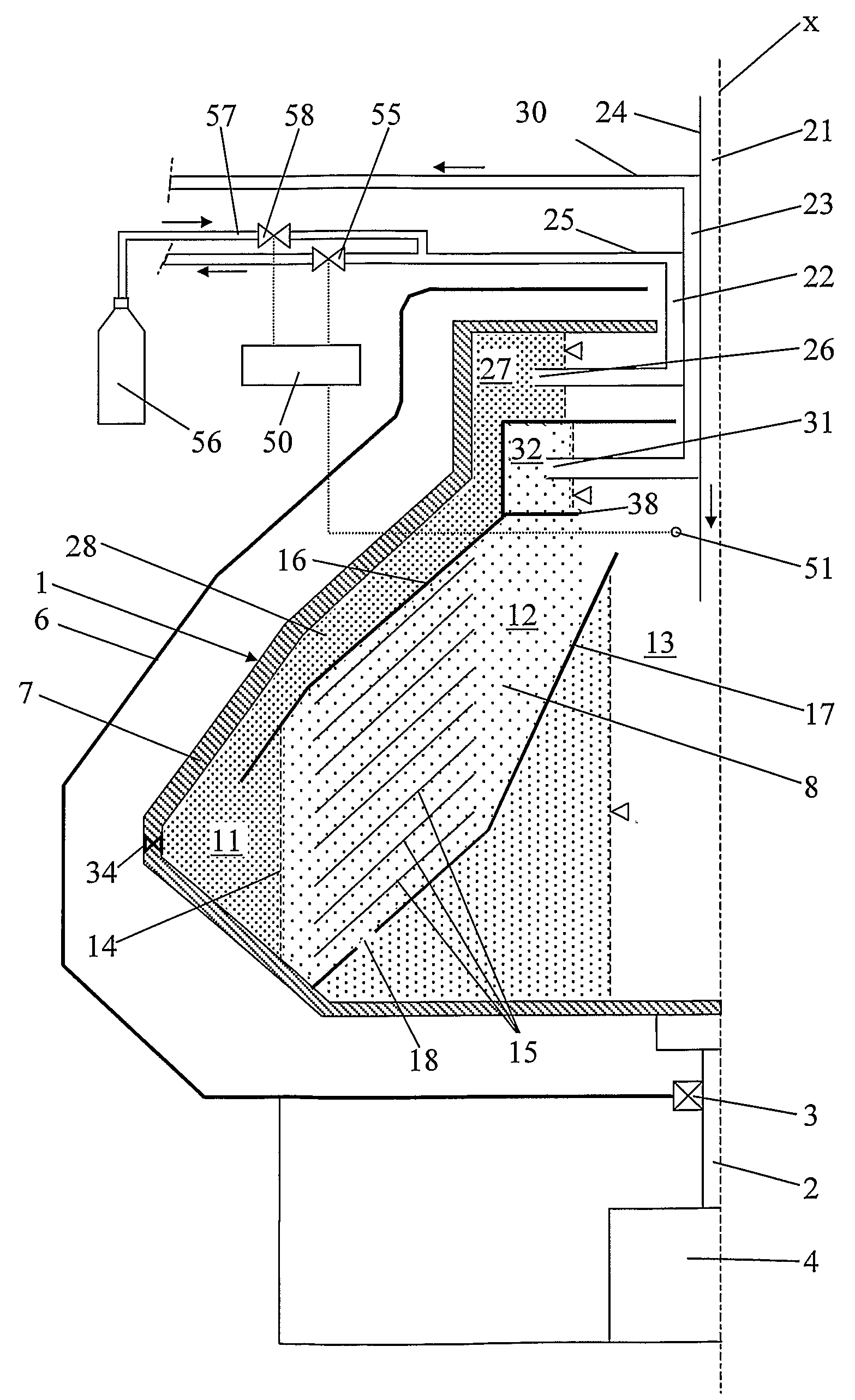
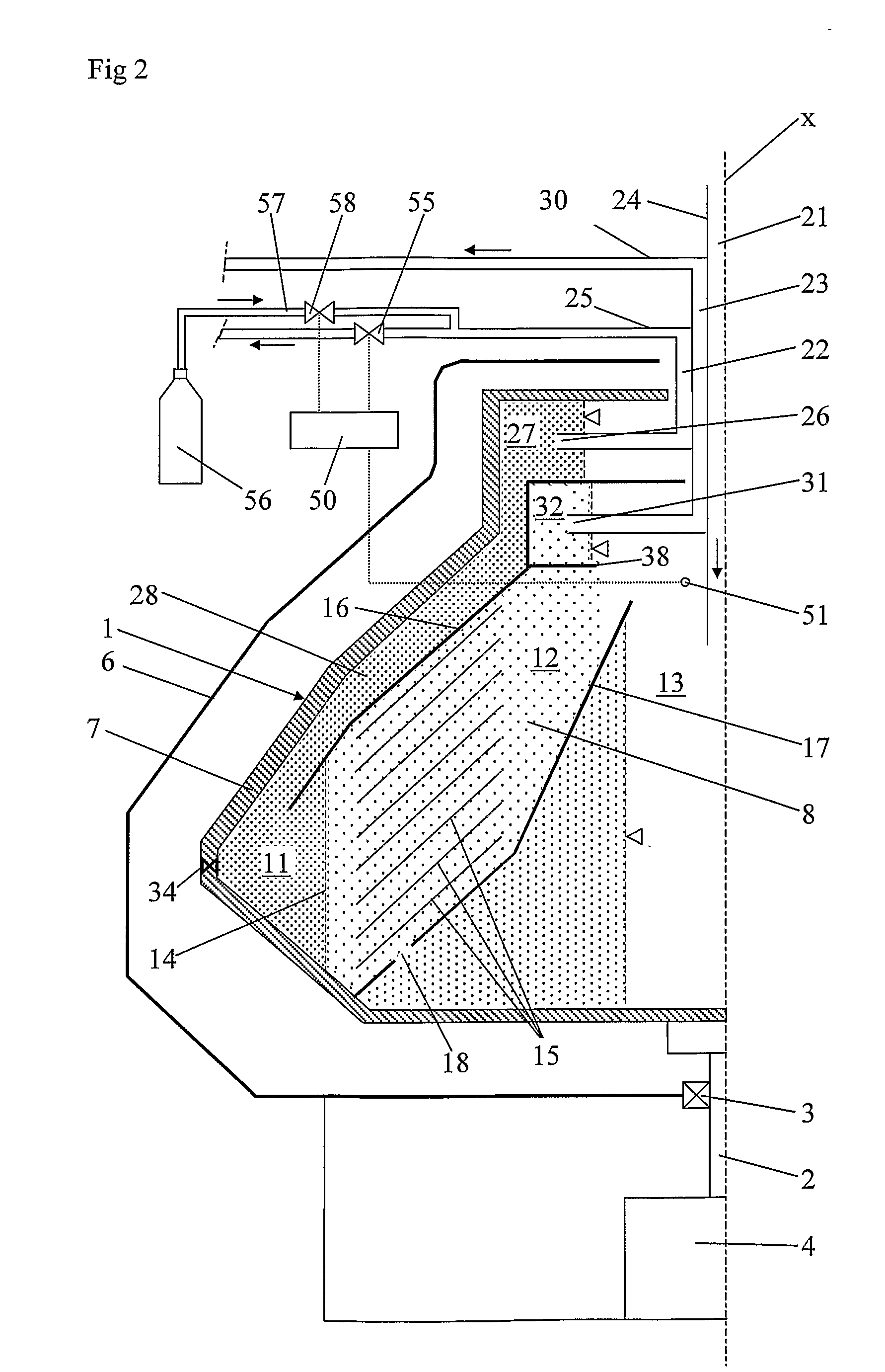
[0039]In the second embodiment, which is disclosed in FIG. 3, an overflow outlet 38 is provided between the radially inner part 12 and the second outlet 23, or more specifically between the radially inner part 12 and the second paring chamber 32.
fourth embodiment
[0040]In the fourth embodiment, which is disclosed in FIG. 5, an overflow outlet 39 is provided between the radially outer part 11 and the first outlet 22, or more specifically between the radially outer part 11 and the first paring chamber 27.
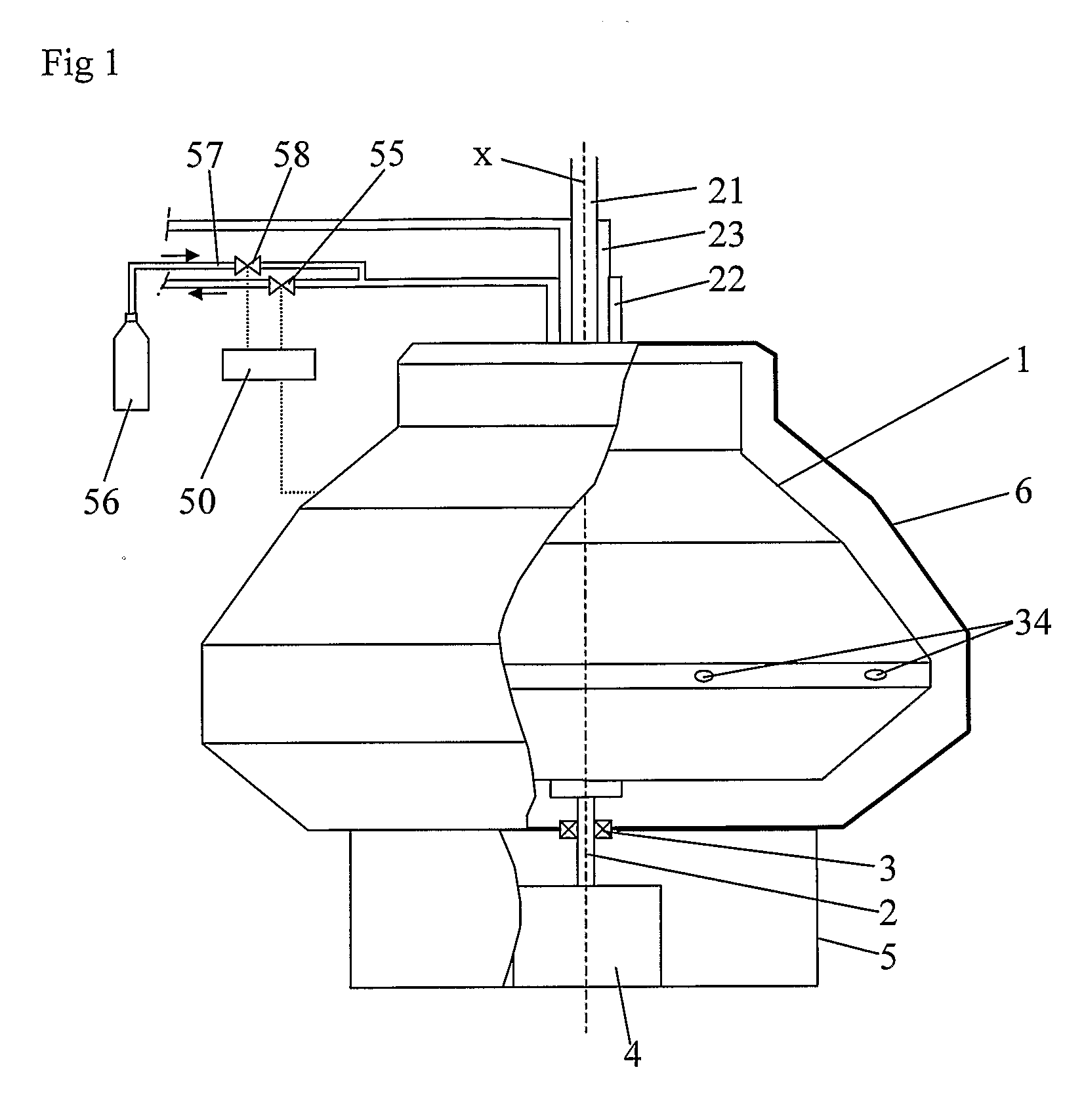
[0041]The centrifugal separator also comprises control equipment arranged to permit during operation control of the interface layer level 14 to a desired radial position by controlling the counter pressure in at least one of the first outlet 22 and the second outlet 23. The control equipment comprises a control unit 50. A sensor is connected to the control unit 50 and provided to sense during operation a parameter related to the gas pressure in the gas-filled space of the separation space 8. In the embodiments disclosed, the sensor is a pressure sensor 51, which senses a gas pressure which is substantially equal to the gas pressure in the central gas-filled space 13 of the separation space 8. In the first and third embodiments, the pressure se...
PUM
| Property | Measurement | Unit |
|---|---|---|
| pressure | aaaaa | aaaaa |
| counter pressure | aaaaa | aaaaa |
| density | aaaaa | aaaaa |
Abstract
Description
Claims
Application Information