
Device for monitoring arterial oxygen saturation

a technology of pulsatile light and oximetry, which is applied in the field of optical-based pulse oximetry, can solve the problems of troublesome detection of pulsatile light, drastic reduction of received light power, and severe limitation of ambulatory use, and achieve the effect of reducing fixation constraints

Inactive Publication Date: 2008-07-17
CSEM CENT SUISSE DELECTRONIQUE & DE MICROTECHNIQUE SA RECH & DEV
View PDF7 Cites 14 Cited by
  • Summary
  • Abstract
  • Description
  • Claims
  • Application Information

AI Technical Summary

Benefits of technology

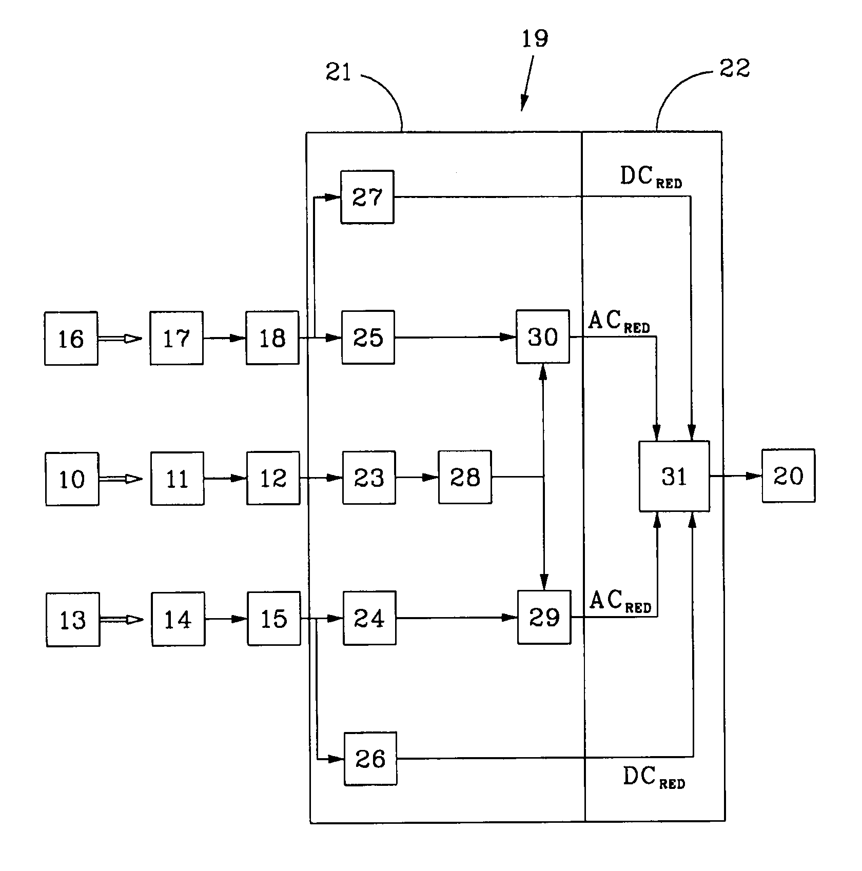
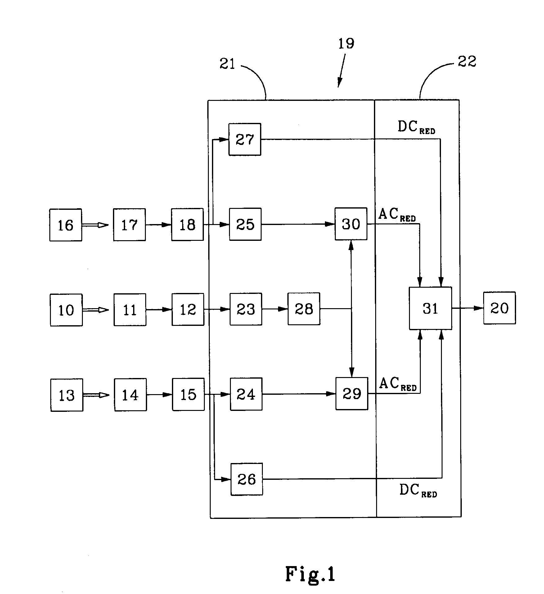
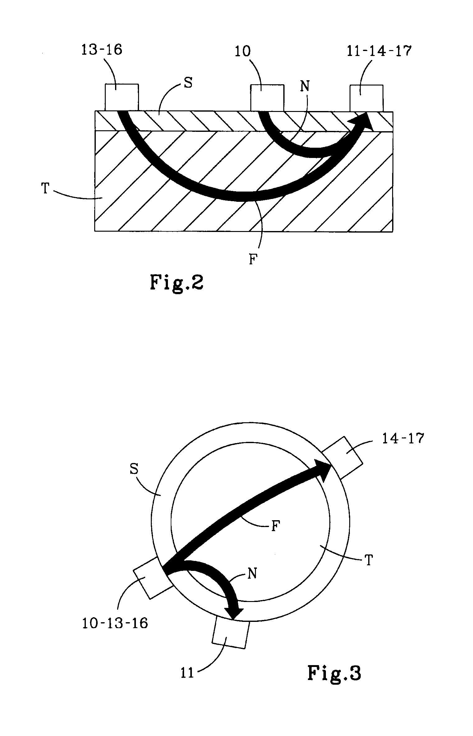
The invention provides a device for monitoring arterial oxygen saturation that overcomes the disadvantages of existing methods. The device uses reflectance optical-probes that can be placed on any body location and does not require an auxiliary ECG recording. The device includes first, second, and third light emitting means that inject light in tissue, with different wavelengths. The device also has first and second light detecting means that collect light from the first and second emitting means, respectively. The first detecting means is located close to the first emitting means, while the second and third detecting means are located further away. The device uses a computing means to denoise the longer distance signals and derive oximetry measurements from them. This approach ensures accuracy and eliminates the risk of double wrong information. The device can be programmed to detect the maximum positions of the short distance signals and perform triggered averaging or estimating the spectral distribution and restoring the output signals.

Problems solved by technology

This configuration virtually allows locating the SpO2 probe at any body placement but creates a severe limitation on its ambulatory use.
However, due to the enlarged light-path, a drastic decrease of the received light power is obtained and the detection of pulsatile light becomes troublesome.
A disadvantage of this method is that it requires that the light intensities measured at the long and short distances depict enough quality to be used in the computation.
Two possibly wrong indications may, therefore, if they are combined, lead to a completely wrong oximetry measurement.

Method used


Image

  • Device for monitoring arterial oxygen saturation
  • Device for monitoring arterial oxygen saturation
  • Device for monitoring arterial oxygen saturation

Examples


Embodiment Construction

[0029]When performing reflectance pulse oximetry, two main reasons justify the increase of the physical separation between optical parts (LEDs and photo-diode).[0030]1. In any pulse oximetry probe, the relative pulse amplitude is a good indicator of the quality of the probe placement. This quality factor, usually depicted as Perfusion Index (PI), is also interpreted as a quantification of the width of the vascular bed traversed by a light beam. It was demonstrated (Y. Mendelson, Noninvasive Pulse Oximetry Utilizing Skin Reflectance Photoplethysmography, IEEE Transactions on Biomedical Engineering, Vol 35, No 10, 1988) that, given a reflectance probe, the PI is linearly increasing with the increase of the physical separation between the optical parts.[0031]2. The probability of direct-light being short-cut from the light sources to the light detector by scattering in the outer part of the skin or / and successive reflection in the probe-skin interface is reduced when both optical eleme...


PUM


Abstract

The present invention concerns an optical based pulse oximetry device comprising:first, second and third light emitting means, for placement on the skin surface of a body part to inject light in a tissue of said part, the wavelengths of the light emitted by said second and third means being different from each otherlight detecting means located at a relatively short distance from said first light emitting means and at relatively long distance from said second light emitting means and said third light emitting means, for collecting at the skin surface light of said emitting means having travelled through said tissue,first computing means for denoising the output signals of said long distance light detecting means from the output signals of said short distance light detecting means, andsecond computing means for deriving oximetry measurements from the denoised output signals of said long distance light detecting means.

Description

BACKGROUND OF THE INVENTION[0001]1) Field of the Invention[0002]The present invention relates to optical-based pulse oximetry. It concerns, more particularly, a pulse oximetry device for monitoring the oxygen saturation (the so called SpO2) of the haemoglobin in arterial blood.[0003]One very interesting application of the invention is the help of subjects requiring continuous SpO2 monitoring, such as, for example, persons suffering from sleep disturbances, neonates, persons having aerospace and aviation activities, alpinists, high altitude sportsmen.[0004]2) Description of Related Art[0005]Since the early works of T. Aoyagi, the principles of pulse oximetry have been established (J. G. Webster, Design of Pulse Oximeters, Institute of Physics Publishing, 1997).1]. Two contrasting wavelength lights (e.g. λr=660 nm and λir=940 nm) are injected in a tissue and a reflected or transmitted part of the photons is further recuperated at the skin surface. The changes in light absorption occur...

Claims


Application Information

Patent Timeline
Patent Type & Authority Applications(United States)
IPC IPC(8): A61B5/1455
CPCA61B5/7207A61B5/14551
Inventor SOLA I CAROS, JOSEPVERJUS, CHRISTOPHEKRAUSS, JENSCHETELAT, OLIVIERNEUMAN, VICTOR
Owner CSEM CENT SUISSE DELECTRONIQUE & DE MICROTECHNIQUE SA RECH & DEV
Learn More