Self returning contamination barrier

a technology of contamination barrier and self-returning, which is applied in the direction of suction device, intravenous device, other medical devices, etc., can solve the problems of membrane collapse or movement, difficult cleaning, and limited use orientation of breast shield, etc., and achieves high-efficiency vacuum transfer and increased pressure

Active Publication Date: 2008-07-17
MEDELA HLDG AG
View PDF99 Cites 42 Cited by
  • Summary
  • Abstract
  • Description
  • Claims
  • Application Information

AI Technical Summary

Benefits of technology

[0028]It is yet another advantage of the present invention to provide a breastpump assembly which isolates parts of the pump in a vacuum line from contamination, such as between a breastshield and a vacuum source in communication with the breastshield via the vacuum line. The vacuum line is in communication with a housing that has a breastshield side and vacuum side. A resilient barrier having a form with a first surface that is, at least in part, generally domelike with an unassembled dome height as measured from a base of the dome to the first surface. The resilient barrier is assembled in the housing in a manner to separate and thereby isolate the breastshield housing side and vacuum housing side in an initial state with a pre-loaded condition for the barrier. The pre-loaded condition of the barrier has an assembled dome height that is less than the unassembled dome height.
[0029]Furthermore, the vacuum realized on the breastshield side follows a generally one to one relationship with the vacuum applied on the vacuum side, after an initial level of vacuum is realized on the vacuum pump side to overcome the pre-load condition. The initial level of vacuum to overcome the pre-load condition can be about 4 to 15 mmHg (negative) in one form of the invention. This yields a highly efficient vacuum transfer across the barrier. The foregoing embodiment can further include a milk conduit structure which conveys milk from the breastshield to a container via a catch chamber and a one-way valve between the catch chamber and the container. The barrier, upon returning to an initial state with a predetermined minimum amount of milk in the catch chamber, generates an increased pressure in the catch chamber relative to the container so as to open the valve and release milk to travel into the container.
[0030]These, together with other objects and advantages will be further understood in the details of the construction and operation of the invention as more fully hereinafter described, reference being had to the accompanying drawings, forming a part hereof, wherein like numerals refer to like parts throughout, in which:

Problems solved by technology

Some breastpumps use gravity and geometry, such as a splashguard, to separate the milk and air (air being the working fluid), but these breastpumps are often difficult to clean, and the orientation of the breastshield in use may be thereby limited.
This differential vacuum causes the membrane to collapse or move.
A problem with some conventional breastpumps of this type is that the membrane may not return to an initial state or position, i.e., it may end up locking or buckling.
A typical issue with these types of pumps is that leakages, evaporation, expulsion of milk and breast extension hysteresis do not ensure that the membrane returns fully to its initial non-collapsed state without the assistance of a positive pressure.
Some conventional manual breastpumps also include a collapsible or movable membrane that has a significant energy loss in “transferring” vacuum from one side to the other.

Method used


Image

  • Self returning contamination barrier
  • Self returning contamination barrier
  • Self returning contamination barrier

Examples


Embodiment Construction

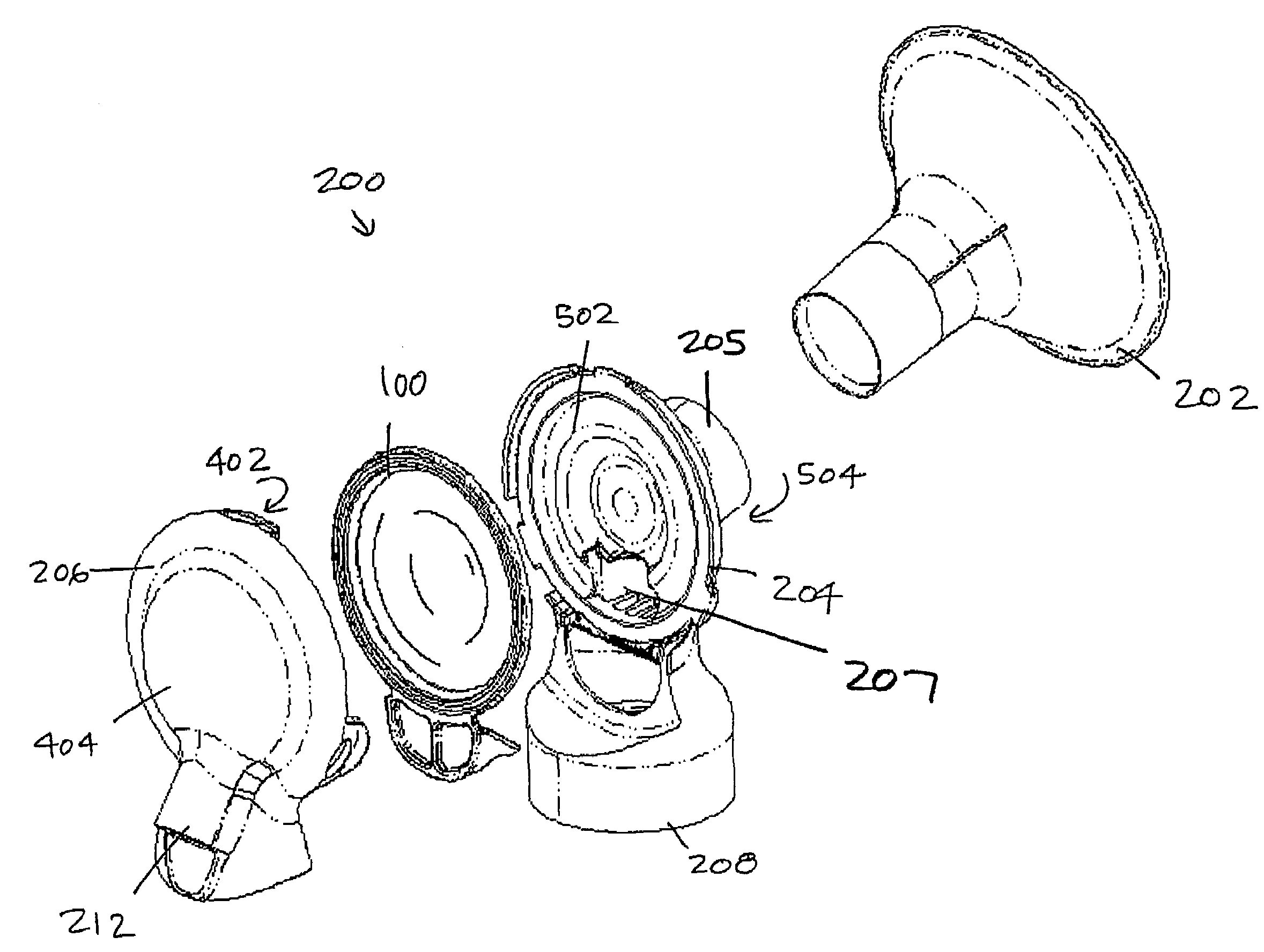
[0045]Although the embodiments of the present invention described herein are directed to breastpump assembly systems, which is the particular environment that the invention finds its origin, it is contemplated that the present invention has various other applications, such as any pump system that requires a barrier to prevent contamination, or that may benefit from a movable membrane that is very efficient in transmitting pressure changes from a volume (or working fluid) on one side to a volume (or working fluid) on the other side.

[0046]The barrier of the present invention works with simple manually operated breastpumps that may provide only suction (and a vent to atmosphere), as well as more complex pumps, such as motorized pumps, and pumps providing both suction and a positive pressure. Thus, while described in particular respects with a source of vacuum, the pressure source could also be a positive pressure moving the barrier.

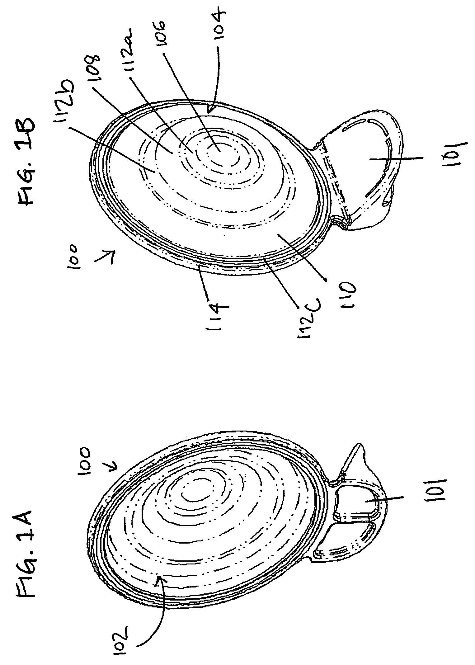
[0047]FIGS. 1A and 1B illustrate a self-returning cont...


PUM

PropertyMeasurementUnit
pressureaaaaaaaaaa
pressureaaaaaaaaaa
atmospheric pressureaaaaaaaaaa

Abstract

A barrier of a vacuum pump prevents contamination from entering a vacuum pump air line. The barrier separates parts of the pump and is moveable between an initial state and a distended state. The barrier is assembled within the pump with a pre-load. When the vacuum source is applied to the barrier, the barrier achieves a distended state and when the vacuum source is released, the barrier incrementally self returns to an initial state. The geometry and material construction of the barrier, along with the pre-load, assists in returning the barrier on its own to the initial state from the distended state.

Description

FIELD OF THE INVENTION[0001]The present invention relates generally to contamination barriers for pumps, and more particularly in one aspect to a breastpump assembly including an improved barrier to prevent milk from entering and possibly contaminating a pumping mechanism for the breastpump.BACKGROUND OF THE INVENTION[0002]Breastpumps are well known, and generally comprise a hood or shield that fits over the breast, a vacuum pump connected to the hood for generating an intermittent vacuum (or negative pressure) within the breastshield, and a receptacle for expressed milk. Negative pressure is pressure below atmospheric pressure. The intermittent suction action of the vacuum pump serves to pull on the breast and nipple and thereby express milk. The expressed milk typically flows from the hood, through a conduit structure and into a collection container, such as a baby bottle, for storage and later use.[0003]Breastpumps can be manually or electrically operated. With manually operated ...

Claims


Application Information

Patent Timeline
Patent Type & Authority Applications(United States)
IPC IPC(8): A61M1/06
CPCA61M1/06A61M1/0049A61M1/062A61M1/064A61M1/78A61M31/00
Inventor LUZBETAK, MARK A.SUTRINA, THOMAS A.PFENNINGER, ERICHBOSSHARD, PATRIK
Owner MEDELA HLDG AG
Why Eureka
Try Eureka