
Electric motor assisted mechanical supercharging system

a technology of electric motors and mechanical supercharging, which is applied in the direction of combustion engines, machines/engines, engine controllers, etc., can solve the problems of high air pressure, increased power generation, and high speed of the supercharging unit, and achieve the effect of increasing the power of the internal combustion engin

Inactive Publication Date: 2008-07-24
ST JAMES DAVID
View PDF4 Cites 39 Cited by
  • Summary
  • Abstract
  • Description
  • Claims
  • Application Information

AI Technical Summary

Benefits of technology

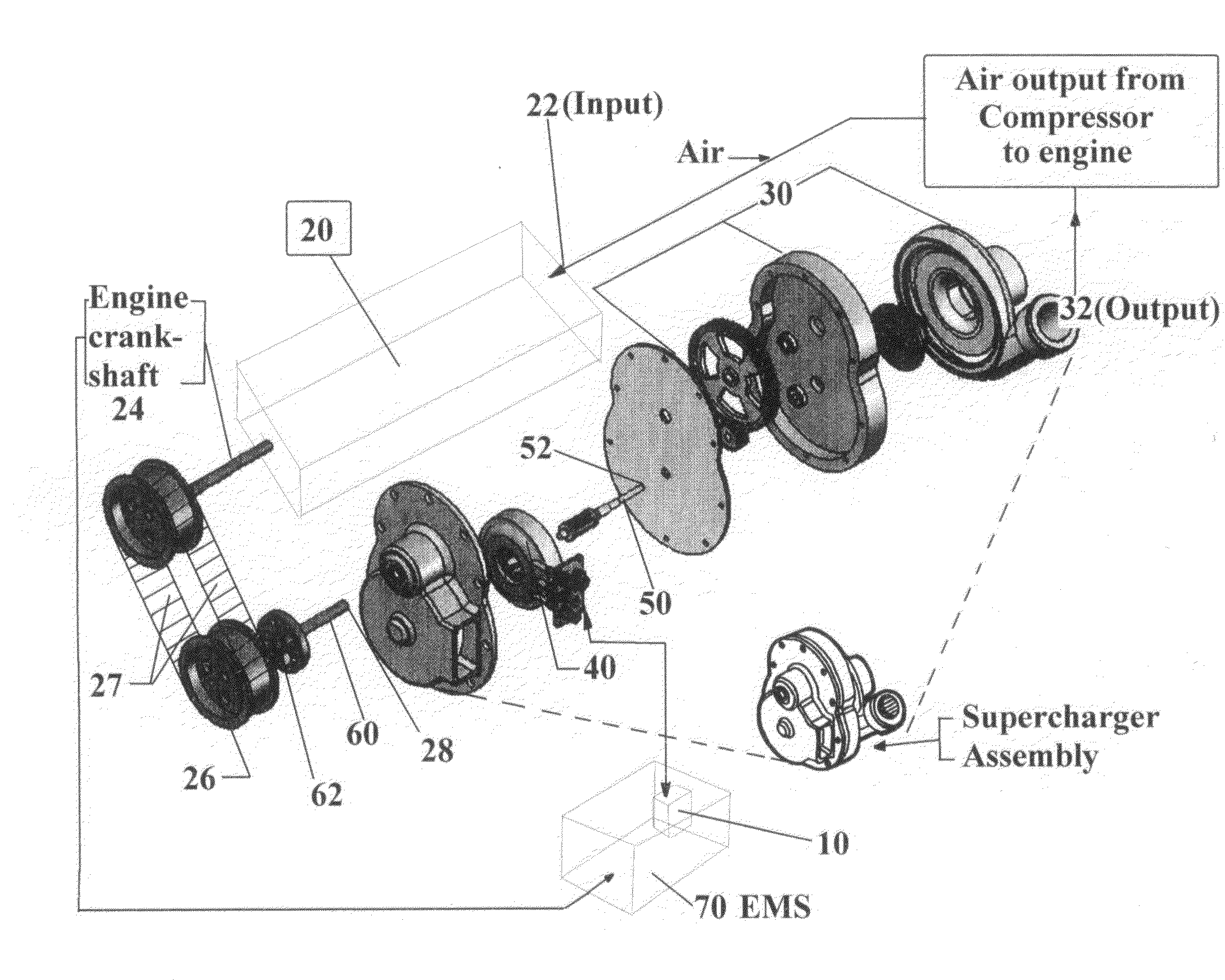
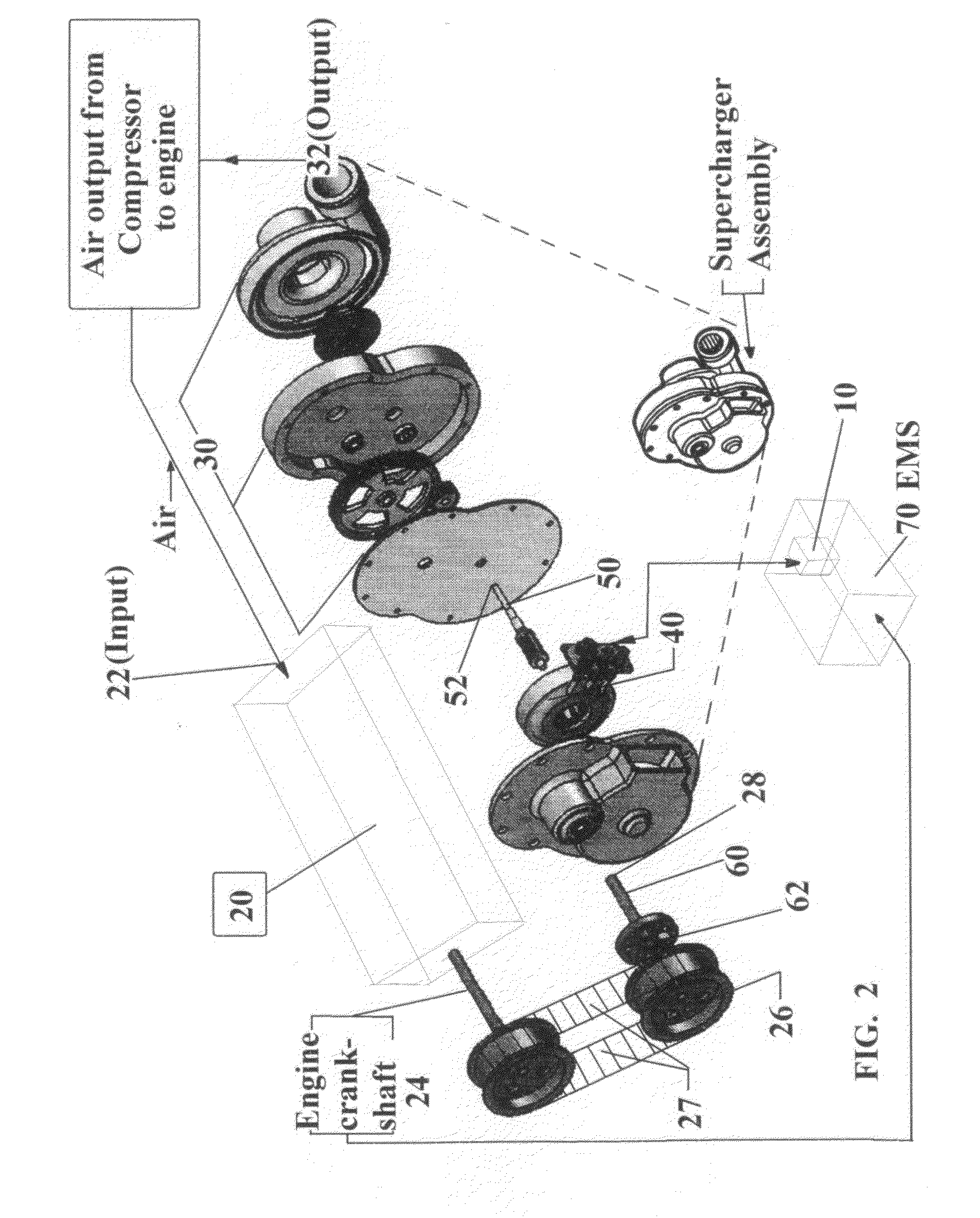
[0007]The present invention addresses the low air pressure problem during low engine RPM by drivingly coupling an auxiliary electric motor / generator to the drive shaft of the compressor in the supercharging system. The auxiliary electric motor / generator is utilized prior to and during low engine RPM to accelerate the compressor to an optimum RPM so that high pressure air can be utilized for increasing the internal combustion engine's power during starting and acceleration of the vehicle.
[0011]A one-way clutch and / or a magnetic clutch placed between the compressor drive shaft and pulley for the belt drive or gear for a gear drive, will disconnect the compressor drive shaft from the engine so that prior to starting the engine the auxiliary electric motor / generator can freely accelerate the compressor to optimum RPM. The electric motor / generator can later be switched off, and the one-way clutch associated with the engine is then engaged so that engine power will thereafter drive the compressor for sustained high power operation.

Problems solved by technology

Therefore, the faster the engine turns, the faster the supercharger speed and therefore higher air pressure and more power is generated.
The drawback of conventional supercharging, however, is the fact that many vehicles need maximum power from start through acceleration, such as from stand still at a traffic light.
In such instances, the engine is turning at low or no RPM, which in turn is rotating the supercharger at a low or no RPM, resulting in very low or no air pressure.
Although generation of power at high engine speeds is beneficial for high vehicle speeds and heavy load carrying applications, the lack of increased power during acceleration is a serious drawback, particularly in applications with a diesel engine when reduced air flow during acceleration usually results in the emission of black smoke.

Method used


Image

  • Electric motor assisted mechanical supercharging system
  • Electric motor assisted mechanical supercharging system
  • Electric motor assisted mechanical supercharging system

Examples


Embodiment Construction

In the Preferred Embodiment

DETAILED DESCRIPTION OF THE APPARATUS

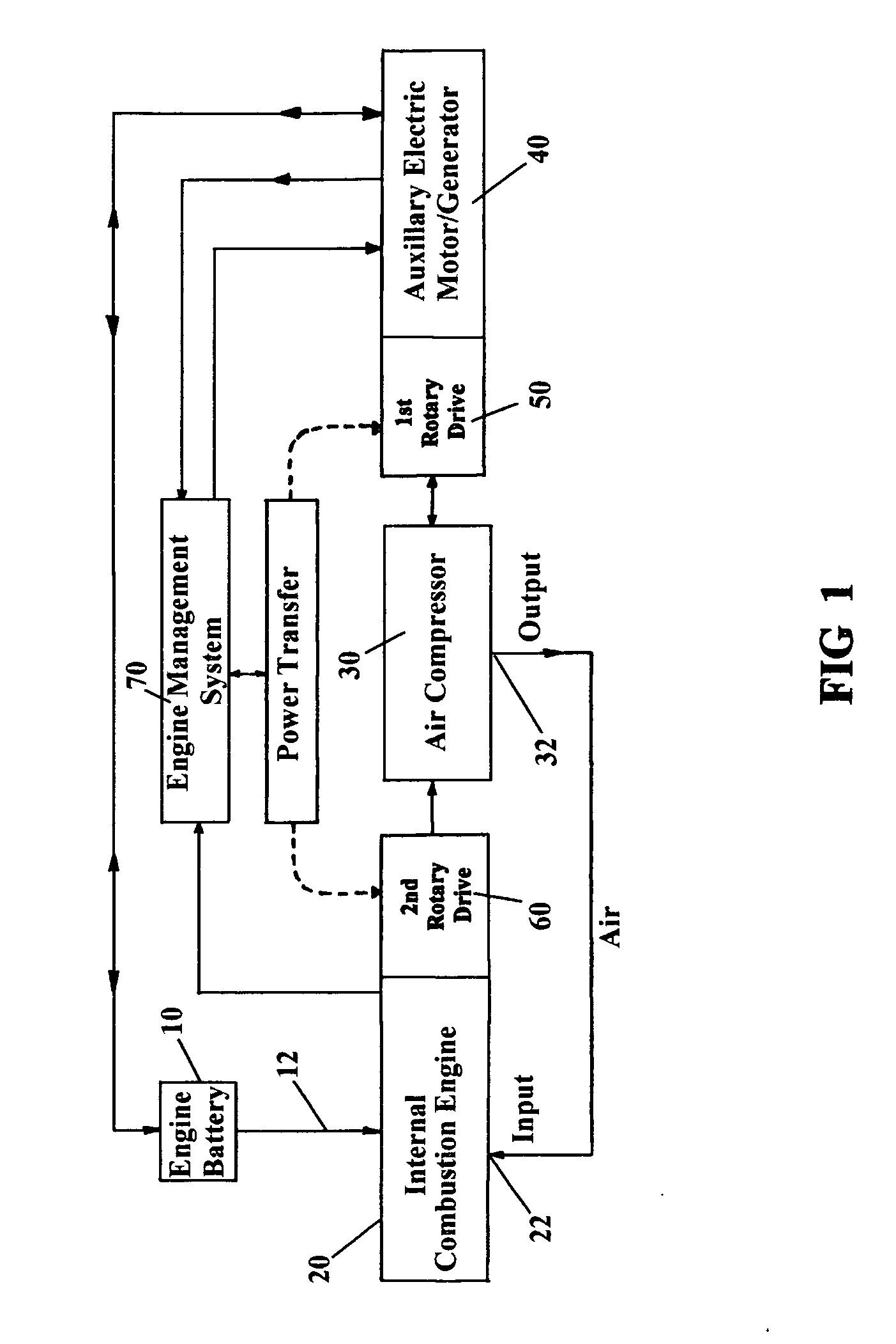
[0050]Referring now to the schematic system drawing of FIG. 1, certain parts of the apparatus are shown in separate boxes, some parts are schematically illustrated only by a solid line, and an important operating function is indicated only by dotted lines.

[0051]An Engine Management System (70) is connected to other parts of the apparatus system by various communication and control lines as needed, some of which are shown, without reference numbers in the FIG. 1 drawing. A Power Transfer function, indicated by dotted lines and controlled by the engine management system, provides the capability of transferring control of rotary power for the air compressor between a first and a second rotary drive means.

[0052]One main function of the engine management system (70) is to make it possible to use the Auxiliary Electric Motor / Generator (40), through its first rotary drive means (50), to drive the Compressor (30) before or afte...


PUM


Abstract

This apparatus and method introduces to the internal combustion engine, with a centrifugal compressor or positive displacement air supercharger, a high speed electric motor / generator which is drivingly coupled to a drive shaft system for the purpose of acceleration and generation of pressurized air at low engine speeds and incorporation of one-way and / or magnetic clutches to provide maximum power to the engine operation at all times. The motor / generator when not driving the supercharger is putting energy back into the engine battery.

Description

CROSS REFERENCE TO RELATED APPLICATIONPriority Claim[0001]This application is a Continuation-in-Part (CIP) of my application Ser. No. 11 / 349,768, filed Feb. 7, 2006, which also claims priority of my Provisional application, Ser. No. 60 / 652,264, filed Feb. 14, 2005 and for which I claim priority under Title 35 USC Section 120.FIELD OF INVENTION[0002]This invention relates generally to optimizing airflow to internal combustion engines to create more power.BACKGROUND OF THE INVENTION[0003]Applications of superchargers in internal combustion engines, whereby pressurized air is generated by means of a centrifugal compressor or a positive displacement air pump such as a roots blower, have been in practice for many years. The power to operate the supercharger is obtained from the engine itself, usually by means of a belt and pulley arrangement or direct gear drive.[0004]Supercharging enables the engine to generate more power by means of a higher volume of air being fed to the engine under ...

Claims


Application Information

Patent Timeline
IPC IPC(8): F02B33/44
CPCF02B33/40F02B33/446Y10T477/26F02B39/10F02B39/12F02B39/04
Inventor ST. JAMES, DAVID
Owner ST JAMES DAVID
Learn More