Image Determination Apparatus, Image Determination Method, and Program, and Image Processing Apparatus, Image Processing Method, and Program

Inactive Publication Date: 2008-07-24
SONY CORP
View PDF2 Cites 23 Cited by
  • Summary
  • Abstract
  • Description
  • Claims
  • Application Information

AI Technical Summary

Benefits of technology

[0021]The noise removing unit may perform noise removal for respective ones of the signals belonging to the plurality of frequency bands detected every pixel by the frequency band signal detecting unit. The noise removal may be performed, e.g., by removing signals indicating the characteristic values being less than a predetermined threshold. Furthermore, the average value calculating unit may calculate the average values of the characteristic values from which noise is removed by the noise removing unit. By being provided with the noise removing unit, the image determination apparatus may remove noise, i.e., any abnormal value, and thus performs more accurate image determination.
[0023]The sample size confidence level setting unit may set the first confidence levels for the sample sizes of the characteristic values for respective ones of the signals belonging to the plurality of frequency bands. The average value confidence level setting unit may set the second confidence levels for the average values for respective ones of the signals belonging to the plurality of frequency bands. The confidence level setting unit may set the third confidence level for the relative value calculated by the relative value calculating unit based on the first confidence levels and the second confidence levels. Then, the image determination unit may determine the image based on the relative value calculated by the relative value calculating unit, and the third confidence level. As a result of this configuration, the image determination apparatus may determine the image independently of any method by which the image is upconverted, and also after eliminating factors responsible for decreasing the confidence levels of determination results on the image.
[0027]As a result of this configuration, prevent erroneous determination may be prevented in the image determination using an input image signal.
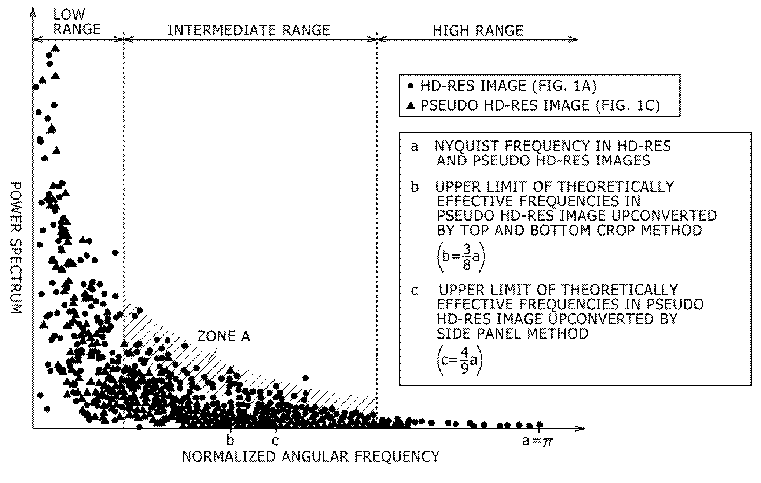
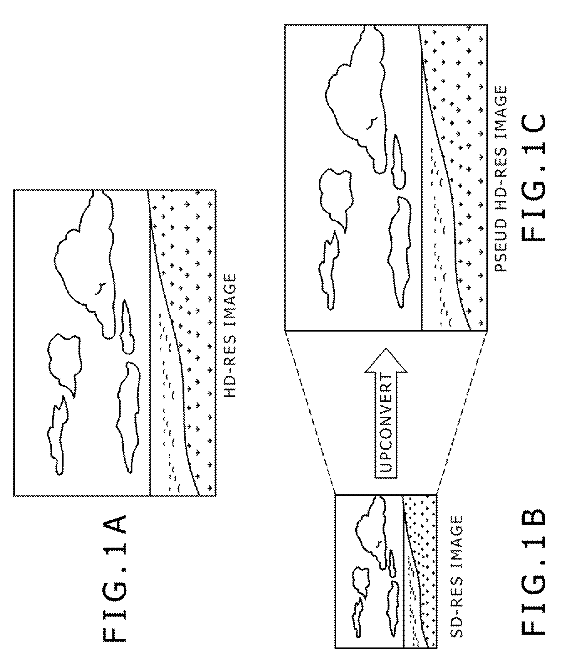
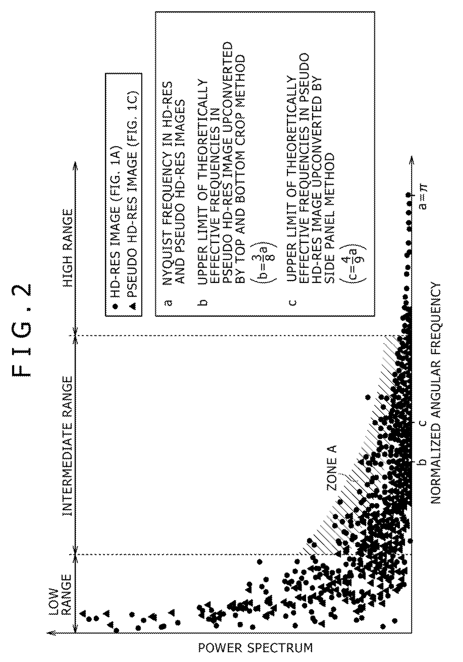
[0037]The average value calculating unit may calculate the average value in each of the plurality of frequency bands, for each of local areas in the whole of an image. Furthermore, the image determination unit may perform image determination based on the relative value calculated by using the average values calculated for each of the local areas. As a result of this configuration, the image determination apparatus may perform image determination on each of the local areas in the whole of the image, even if an HD-resolution image portion and an image portion upconverted from an SD-resolution image are mixed in an image for determination, and thus may perform image determination accurately.

Problems solved by technology

However, the above-mentioned image determination technology by detection of side panels requires that side panel signals representing ineffective areas be only signals below a predetermined threshold.
Therefore, with this image determination technology by detection of side panels, it is difficult to determine the image unless the side panel signals added to an image upconverted from an SD-resolution image into an HD-resolution image are signals below a predetermined threshold.
Therefore, the above-mentioned image determination technology by detection of side panels is incapable of determination an image when the image signal contains no side panel signals.
Furthermore, the above-mentioned image determination technology involving calculation of an average brightness in addition to detection of side panels is also based on detection of side panels, and hence may neither determine nor process an image when the image signal contains no side panel signals.

Method used


Image

  • Image Determination Apparatus, Image Determination Method, and Program, and Image Processing Apparatus, Image Processing Method, and Program
  • Image Determination Apparatus, Image Determination Method, and Program, and Image Processing Apparatus, Image Processing Method, and Program
  • Image Determination Apparatus, Image Determination Method, and Program, and Image Processing Apparatus, Image Processing Method, and Program

Examples


first embodiment

of Image Type Determination Section

Image Determination Apparatus

[0100]FIG. 5 is a diagram illustrating an image type determination section 100 according to a first embodiment of the image type determination section.

[0101]Referring to FIG. 5, the image type determination section 100 according to the first embodiment of the image type determination section has a frequency band signal detecting unit 110, a noise removing unit 120, an average value calculating unit 130, a relative value calculating unit 140, and an image determination unit 150.

[0102]The image type determination section (image determination apparatus) 100 may have, e.g., a control unit, not shown, that is configured with an MPU (Micro Processing Unit) or the like and may control the whole image type determination section 100, a ROM (Read Only Memory), not shown, in which programs and control data, such as operation parameters, used by the control unit are recorded, a RAM (Random Access Memory), not shown, that temporaril...

second embodiment

of Image Type Determination Section

Image Determination Apparatus

[0125]In the image type determination section 100 according to the first embodiment of the image type determination section (image determination apparatus), a configuration has been described in which a single relative value is calculated as the HD level. Next, an image determination apparatus (image type determination section) will be described which performs image determination by a configuration for calculating a plurality of relative values as HD levels. FIG. 6 is a diagram illustrating an image type determination unit 200 according to a second embodiment of the image type determination unit.

[0126]Referring to FIG. 6, the image type determination section 200 according to the second embodiment of the image type determination section has a frequency band signal detecting unit 210, a noise removing unit 220, an average value calculating unit 230, a relative value calculating unit 240, and an image determination unit 25...

third embodiment

of Image Type Determination Section

Image Determination Apparatus

[0142]Next, an image type determination unit (image determination apparatus) according to a third embodiment of the image type determination unit will be described. FIG. 7 is a diagram illustrating an image type determination section 300 according to the third embodiment of the image type determination section.

[0143]Referring to FIG. 7, the image type determination section 300 according to the third embodiment of the image type determination section has a configuration and a function similar to those of the image type determination section 200 according to the second embodiment of the image type determination section shown in FIG. 6. When compared with the image type determination section 200, reference values differ which are used when first relative value calculating means 342 to (n−1)-th relative value calculating means 344 of a relative value calculating unit 340 calculate respective relative values.

[0144]Also, the ...


PUM


Abstract

An image determination apparatus includes a frequency band signal detecting unit, an average value calculating unit, a relative value calculating unit, and an image determination unit. The frequency band signal detecting unit detects signals belonging to a plurality of frequency bands, from an image signal. The average value calculating calculates average values for respective ones of the signals belonging to the plurality of frequency bands detected by the frequency band signal detecting unit. Each of the average values is a characteristic value equivalent to an amplitude. The relative value calculating unit calculates a relative value of one of the average values to another of the average values, among the average values calculated for respective ones of the plurality of frequency bands. The image determination unit for determining an image based on the relative value calculated by the relative value calculating unit. The image determined is subject to image-processing.

Description

BACKGROUND OF THE INVENTION[0001]1. Field of the Invention[0002]The present invention relates to an image determination apparatus, an image determination method, and a program for causing a computer to execute the image determination, and an image processing apparatus, an image processing method, and a program for causing a computer to execute the image processing.[0003]2. Description of Related Art[0004]Recently, along with the start of digital broadcasting, high-definition resolution (HD-resolution) image signals are transmitted from broadcasting stations or the like. However, image signals transmitted from the broadcasting stations or the like are not all HD-resolution image signals, but may in some cases contain pseudo HD-resolution image signals which are upconverted from the standard-definition resolution (SD-resolution) image signals used in the traditional analog broadcasting, into HD-resolution image signals.[0005]For upconverting an SD-resolution image into an HD-resolutio...

Claims


Application Information

Patent Timeline
IPC IPC(8): H04N5/14
CPCG06T5/10G06T5/002G06T3/4084H04N7/0135G06T5/70
Inventor SUZUKI, MASARUOGATA, MASAMIUEDA, KAZUHIKO
Owner SONY CORP
Why Eureka
Try Eureka