Eureka AIR delivers breakthrough ideas for toughest innovation challenges, trusted by R&D personnel around the world.

Scanner Device

Active Publication Date: 2008-07-24
X RITE SWITZERLAND
View PDF15 Cites 8 Cited by
  • Summary
  • Abstract
  • Description
  • Claims
  • Application Information

AI Technical Summary

Benefits of technology

[0010]It is an objective of this invention to improve a scanner device of the generic type so that it is s

Problems solved by technology

Measuring small measurement fields cleanly at a high scanning speed requires a more complex design of measuring optics than is available in the prior art.

Method used


Image

  • Scanner Device
  • Scanner Device
  • Scanner Device

Examples


Embodiment Construction

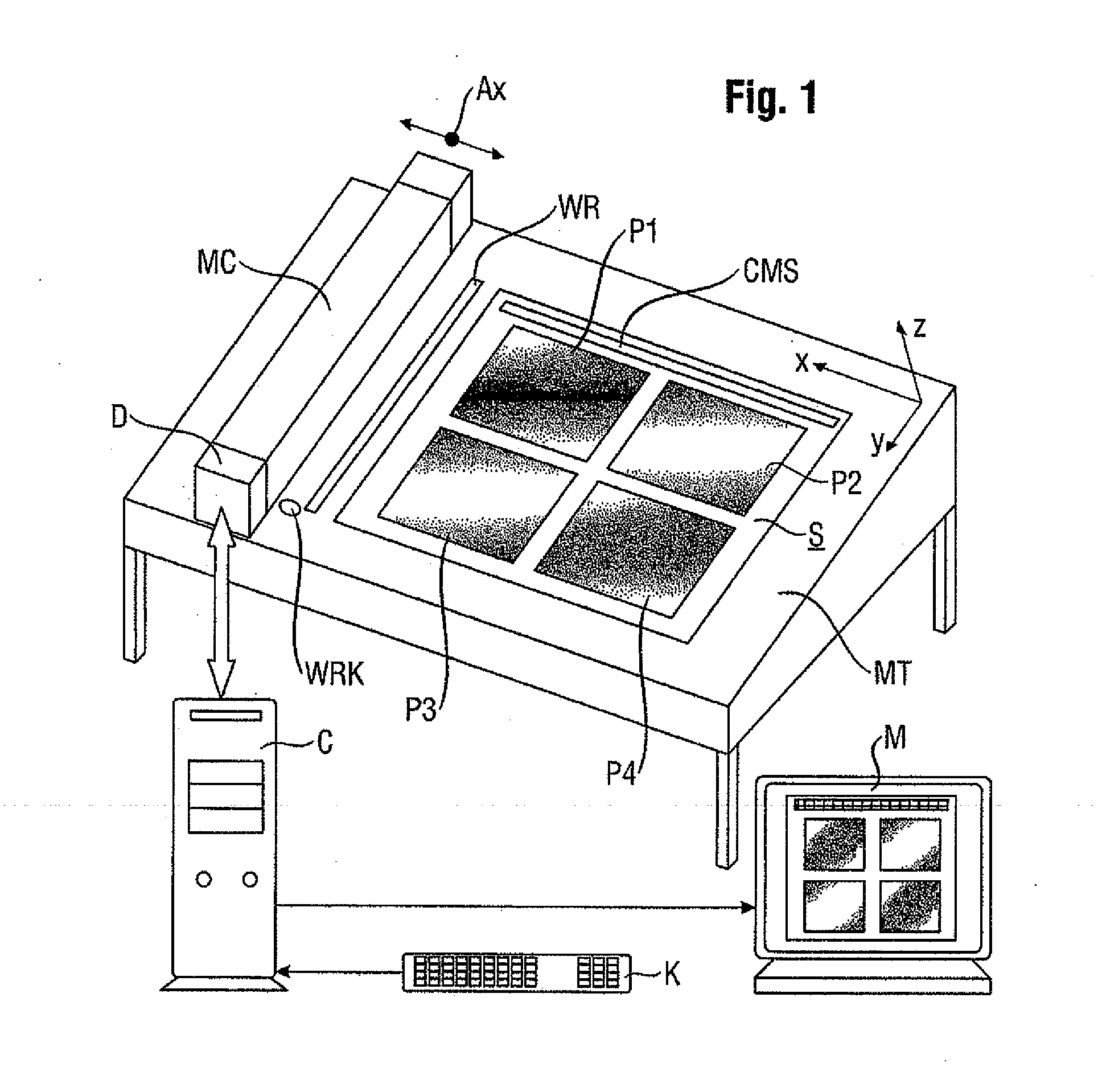
[0022]In terms of its general construction, the scanner device proposed by the invention conforms to standard measuring apparatus, of the type typically used in the graphics industry for taking photoelectric measurements of printed sheets taken from a printing process on the basis of pixels. The scanner device comprises a sub-structure in the form of a measuring table MT with what is usually an inclined rectangular surface, on which the measured object S—the printed sheet to be measured—can be positioned. The measuring table therefore provides a support surface for the measured object. The printed sheet S typically contains a few (in this instance four, for example) graphic images P1-P4 and a (or several) color measuring strips CMS. In order to position the measured object S, stops are provided on the measuring table MT, although these are not illustrated. The measured object S is preferably secured on the measuring table MT by electrostatic means or by means of known suction mechan...


PUM


Abstract

A scanner device for measuring the color properties of a measured object pixel by pixel has a support surface for the measured object, a color measuring head, a drive unit for moving the color measuring head above the support surface in at least one dimension thereof and for adjusting the height of the color measuring head in the direction perpendicular to the support surface, as well as a measurement and drive control unit which activates the drive unit and co-operates with the color measuring head. It is also equipped with an electronic distance control system which adjusts the distance of the color measuring head above the measurement point in the direction perpendicular to the support surface to a desired measuring distance for every measurement point by means of the drive unit. The electronic distance control system works with measurement values generated by the color measuring head and distance values computed from them. The scanner device is suitable for running high-precision measurements on even the smallest measurement fields without contact and no separate measurement sensor is needed for the distance control system.

Description

BACKGROUND OF THE INVENTION[0001]The invention relates to a scanner device for measuring the color properties of a measured object pixel by pixel by means of a color measuring head of the type with a support surface for the measured object and a drive unit for moving the color measuring head above the support surface in at least one dimension thereof and for adjusting the height of the color measuring head in the direction perpendicular to the support surface, and having a measurement and drive control unit which activates the drive unit and co-operates with the color measuring head.[0002]Published international patent application WO 2006 / 045621 A1 provides a detailed description of an automated measuring system for quality control and for controlling the color of a printing machine. It essentially comprises a measuring table on which a printed sheet to be measured can be placed, and a measuring unit comprising a beam-shaped line scanner and an individual color measuring head. The l...

Claims


Application Information

Patent Timeline
IPC IPC(8): G01B11/14G01J3/46
CPCG01J3/02G01J3/027G01J3/0278G01J3/50H04N2201/0456H04N1/00002H04N1/04H04N2201/0436G01J3/502
Inventor EHBETS, PETERKOHLBRENNER, ADRIAN
Owner X RITE SWITZERLAND
Why Eureka
Eureka Blog
Learn More