Burst mode operation in a DC-DC converter

a dc-dc converter and burst mode technology, applied in the field of burst mode converters, can solve problems such as inconvenience to users and generation of audible nois

Active Publication Date: 2008-07-24
SEMICON COMPONENTS IND LLC
View PDF3 Cites 142 Cited by
  • Summary
  • Abstract
  • Description
  • Claims
  • Application Information

AI Technical Summary

Benefits of technology

[0016]An embodiment of the PWM controller may include: a logical operator for performing a logical operation on the burst mode control signal and a pulse signal to generate a first signal; an on time pulse generator for generating the pulse signal; a second comparator for receiving the first voltage and the sense voltage, and generating a second signal according to the result of comparing the first voltage and the sense voltage; and an SR flip-flop for receiving the first signal through a set terminal and the second signal through a reset terminal, and generating a gate driver control signal according to logical values of the first signal and the second signal.
[0017]The first voltage is less than the peak of the sawtooth waveform signal, and a frequency of

Problems solved by technology

The conventional hysteretic burst mode converter has a simple structure, but it generates audible noise.
The group frequency bandwidth (1 Khz-14 Kh

Method used


Image

  • Burst mode operation in a DC-DC converter
  • Burst mode operation in a DC-DC converter
  • Burst mode operation in a DC-DC converter

Examples


Embodiment Construction

[0030]In the following detailed description, only certain exemplary embodiments are shown and described, simply by way of illustration. As those skilled in the art will realize, the described embodiments may be modified in various different ways, all without departing from the spirit or scope of the present invention. Accordingly, the drawings and description are to be regarded as illustrative in nature and not restrictive. Like reference numerals designate like elements throughout the specification.

[0031]Throughout the specification and the claims that follow, when it is described that an element is “coupled” to another element, the element may be “directly coupled” to the other element or “electrically coupled” to the other element through one or more additional elements.

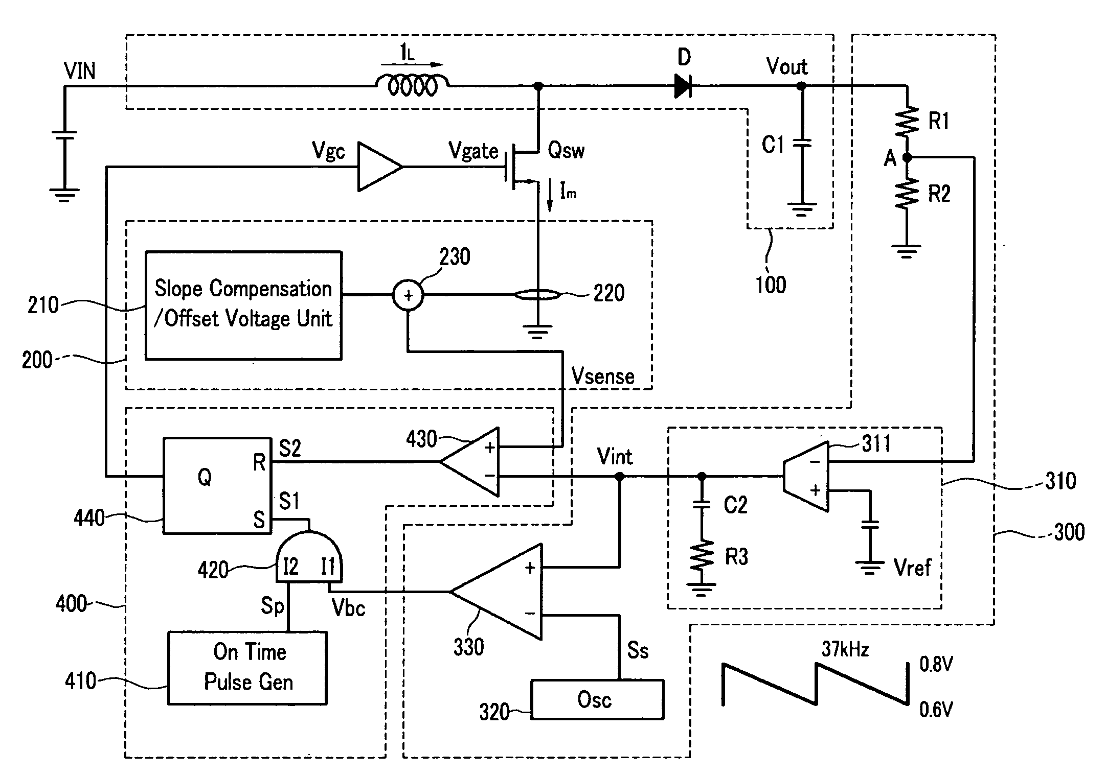
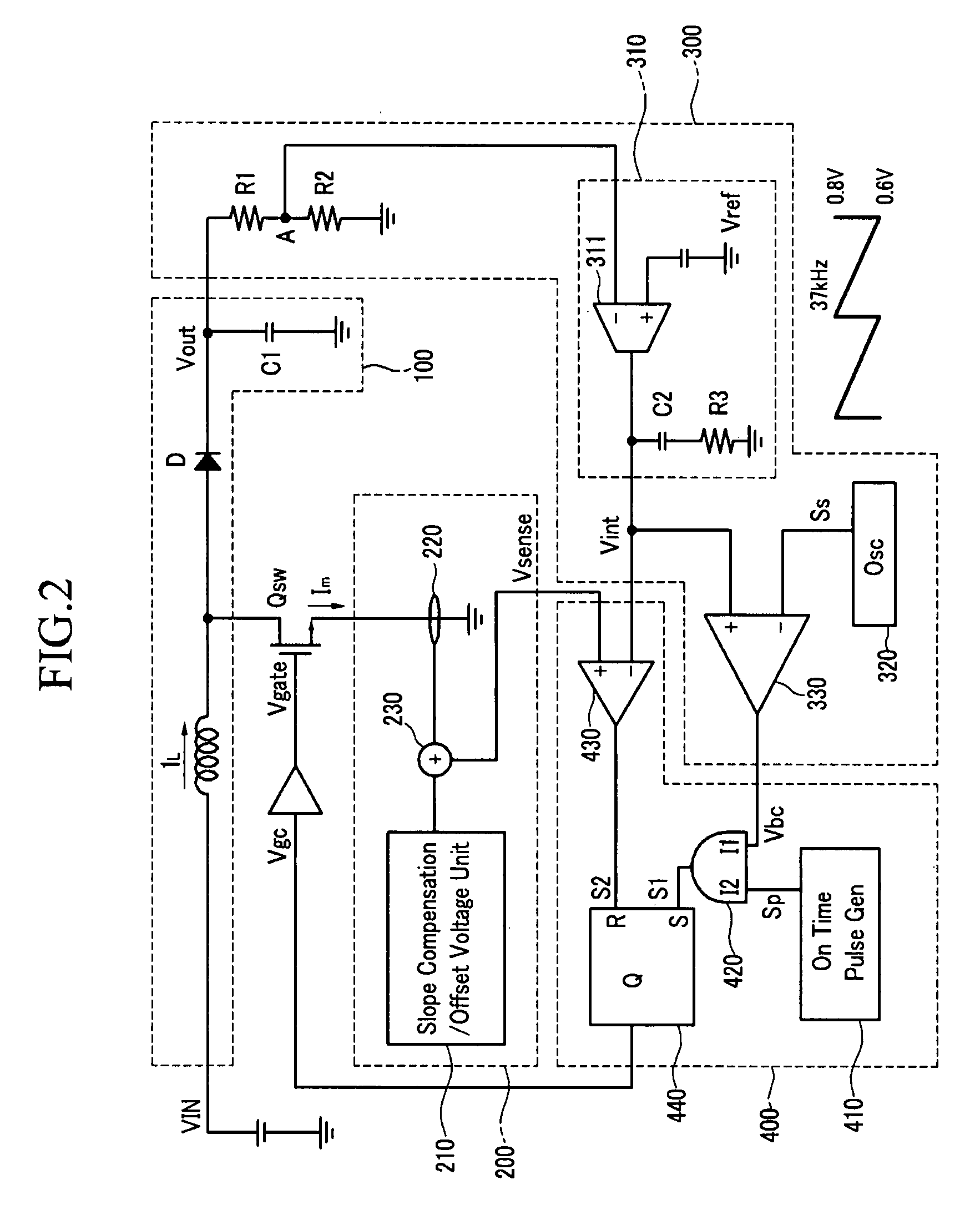
[0032]A converter and its driving method will be described in detail with reference to the drawings. A switching operation will indicate an operation in which a main switch is turned on, then turned off after main...


PUM


Abstract

The present invention relates to a converter and a driving method thereof. The converter uses an input voltage to generate an output voltage by a main switch's switching and applies power to a load, senses the current flowing to the main switch to generate a sense voltage, uses a first voltage corresponding to the current applied to the load and a sawtooth waveform signal having a first frequency to control a group frequency of the burst mode, controls the main switch's turn-on timing, and uses the first voltage and the sense voltage to determine whether to turn off the main switch, thereby controlling the main switch's switching. The converter determines the start and end of the period for switching according to the result of comparing the first voltage and the sawtooth waveform signal. Therefore, a converter for having a constant group frequency, preventing audible noise, and preventing output voltage ripple, and a driving method thereof, are provided.

Description

CROSS-REFERENCE TO RELATED APPLICATION[0001]This application claims priority to and the benefit of Korean Patent Application No. 10-2007-0005484 filed in the Korean Intellectual Property Office on Jan. 18, 2007, the entire content of which is incorporated herein by reference.BACKGROUND[0002]1. Field of the Invention[0003]The present invention relates to a converter. More particularly, the present invention relates to a burst mode converter and a driving method thereof.[0004]2. Description of the Related Art[0005]A burst mode is a driving mode for a converter to output power through switching for a predetermined time, stop the switching for another predetermined time, and repeat the process so as to reduce power consumption when a load connected to the converter is low.[0006]The conventional hysteretic burst mode converter has a simple structure, but it generates audible noise. The hysteretic burst mode converter uses a hysteresis comparator. In the case of using the hysteresis compa...

Claims


Application Information

Patent Timeline
IPC IPC(8): H02M7/757
CPCH02M3/156H02M3/155
Inventor JUNG, SANG-HWALEE, KYUNG-GOO
Owner SEMICON COMPONENTS IND LLC
Why Eureka
Try Eureka