Fiber pulse laser apparatus and method of control the same

a laser apparatus and fiber pulse technology, applied in the direction of electrical apparatus, wave amplification devices, laser details, etc., can solve the problems of laser oscillators that do not employ mo-pa, laser oscillators with mo-pa, and small outputs of first several pulses, etc., and achieve the effect of increasing the cost of the apparatus

Active Publication Date: 2008-07-24
THE FUJIKURA CABLE WORKS LTD
View PDF6 Cites 3 Cited by
  • Summary
  • Abstract
  • Description
  • Claims
  • Application Information

AI Technical Summary

Benefits of technology

[0024]In addition, according to the aspects of the present invention, as shown in FIG. 2, since the first pulse can be equalized in magnitude with the second and subsequent pulses, an optical amplifier or a fiber laser that employs the control method of the present invention can stabilize a pulse output.
[0025]In addition, in the present invention, it is possible to operate the laser apparatus with the same sequence in any of these cases, without requiring a complicated pulse control, and to stabilize the pulse output, and without an increase in the apparatus costs.

Problems solved by technology

In general, MO-PA type laser apparatuses have a disadvantage in that outputs of first several pulses become small immediately after the laser is started with pulse operation.
On the contrary, other types of laser oscillators that do not employ MO-PA type have A different disadvantage in that only the first pulse is increased.
The cause of the disadvantage of the first pulse in the MO-PA type laser apparatus is a slow start-up time of an amplifier (PA).
In addition, although the MO unit can start slightly earlier than the PA unit, if the start-up time is shortened, the start-up time of the MO unit may cause any disadvantages in that the start-up time of the MO unit may present a bottleneck, thereby making it difficult to obtain any advantages from a reduction in the start-up time.
This related-art technique cannot provide a solution to the essential problem that it takes a long time for the LD to produce a desired output and stabilize a population inversion of an amplification medium, thus giving no advantages with respect to the following points:To make the pulse peak value constant from “first pulse” under all operation conditions.To reduce the start-up time of the MO unit.

Method used


Image

  • Fiber pulse laser apparatus and method of control the same
  • Fiber pulse laser apparatus and method of control the same

Examples


example 1

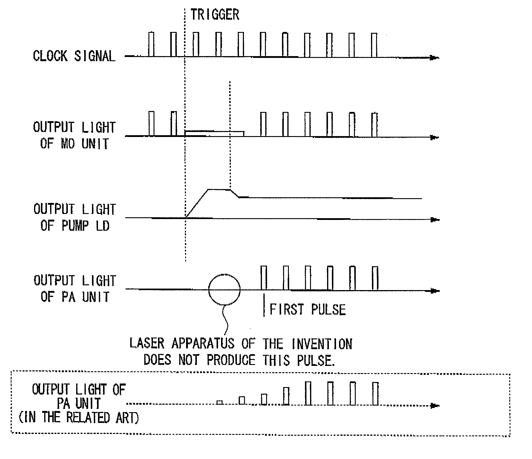
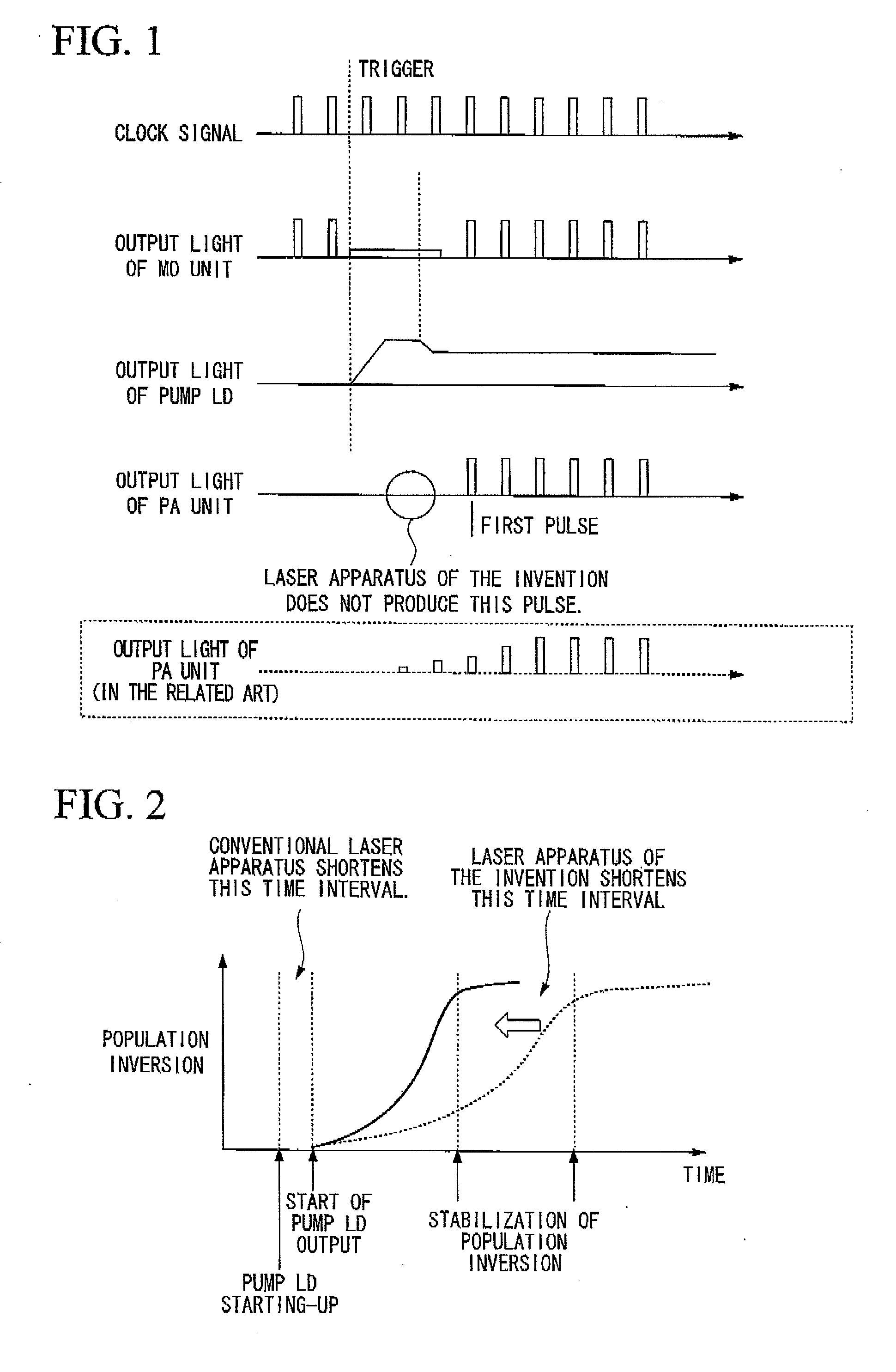
[0046]In a fiber laser that can obtain an average laser output of 10 W when the excitation power of a PA is 30 W and when the CW output of an MO is 0 mW (no output) with the PA excitation power of 30 W in the CW operation, the time (in the unit of μs) taken until a first pulse is equalized in magnitude with second and subsequent pulses after a plump LD outputs a power of 30 W was examined. Table 1 shows the results.

TABLE 1Time taken to output firstRepetition frequencypulse100 kHz 30 μs50 kHz70 μs30 kHz100 μs 20 kHz180 μs 

[0047]In this example, when a Q switch pulse operation started after the MO maintained a CW output of 0 mW for only the time shown in Table 1, the first pulse was equalized in magnitude with the second pulse (with the margin of error of ±5%).

[0048]The result shown in Table 1 was empirically obtained based on the excitation power of the PA unit, the CW output of the MO unit, and a desired output.

example 2

[0049]Using the same fiber laser as Example 1, the same control as Example 1 was carried out to equalize the first pulse in magnitude with the second and subsequent pulses under an operation condition of an average output of 15 W. Similarly to Example 1, when the CW output of the MO is 0 mW with the PA excitation power of 30 W, the time (in the unit of μs) taken to output the first pulse was examined. Table 2 shows the results.

TABLE 2Time taken to output firstRepetition frequencypulse100 kHz 15 μs50 kHz35 μs30 kHz50 μs20 kHz90 μs

[0050]The first pulse output after elapse of the time shown in Table 2 was substantially equalized in magnitude with the second pulse.

[0051]From the comparison between Example 1 and Example 2, it can be seen that the average output in the normal operation is in proportion to the time taken to output the first pulse.

[0052]If the CW output, which was set to be 0 mW in Examples 1 and 2, was increased to 10 mW or above, the time taken to output the first pulse b...


PUM


Abstract

A method of controlling a pulse output in a master oscillator-power amplifier type fiber pulse laser apparatus comprising a master oscillator unit and a power amplifier unit connected to the master oscillator unit, includes starting the master oscillator unit before starting the power amplifier unit.

Description

BACKGROUND OF THE PRESENT INVENTION[0001]1. Field of the Present Invention[0002]The present invention relates to a fiber pulse laser apparatus, and more particularly, to a method of controlling pulse outputs such that a first pulse output is equalized in magnitude with second and subsequent pulse outputs in a pulse laser that oscillates pulses through a combination of a master oscillator and an optical amplifier (hereinafter, referred to as an MO-PA type laser apparatus), and a fiber pulse laser apparatus that controls a pulse output according to the control method.[0003]Priority is claimed on Japanese Patent Application No. 2007-12546, filed Jan. 23, 2007, the content of which is incorporated herein by reference.[0004]2. Description of Related Art[0005]In the related art, for example, MO-PA type laser apparatuses are disclosed in various documents.[0006]Among these disclosures, Japanese Patent No. 2658351 discloses a technique for controlling a strength ratio of a peak value of a f...

Claims


Application Information

Patent Timeline
Patent Type & Authority Applications(United States)
IPC IPC(8): H01S3/13
CPCH01S3/06754H01S3/10015H01S3/2308H01S3/1301H01S3/11H01S3/1001H01S3/1123
Inventor NAKAI, MICHIHIRO
Owner THE FUJIKURA CABLE WORKS LTD
Why Eureka
Try Eureka