
Echo canceler and echo canceling method

a canceler and echo technology, applied in the field of echo cancelers and echo canceling methods, can solve the problems of reducing the speed of convergence in an environment with little background noise, affecting the performance of echo cancelers, and affecting the accuracy of echo replica signals, etc., to achieve faster convergence of filter coefficients and step sizes.

Active Publication Date: 2008-07-24
OKI ELECTRIC IND CO LTD
View PDF6 Cites 32 Cited by
  • Summary
  • Abstract
  • Description
  • Claims
  • Application Information

AI Technical Summary

Benefits of technology

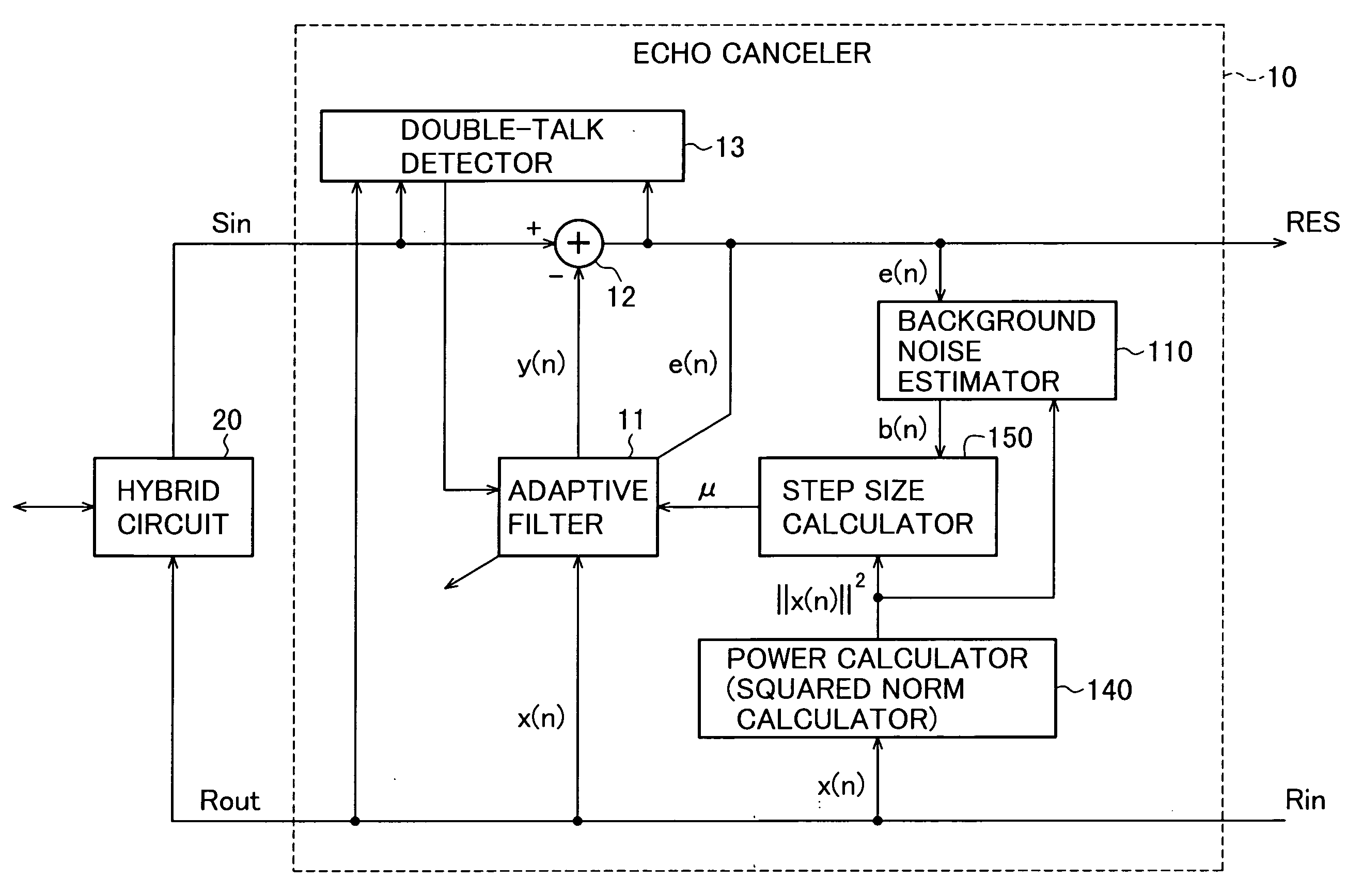
[0039]An object of the present invention is to provide an echo canceler and echo canceling method with improved echo canceling performance in environments with much background noise, without reducing the speed of convergence in environments with little background noise.
[0042]According to this scheme, the step size is reduced during periods of high near-end background noise, causing the filter coefficients to be altered by smaller amounts, so that echo cancellation is not disrupted by effects of the background noise. During times of lower near-end background noise, a larger step size is used, permitting faster convergence of the filter coefficients.

Problems solved by technology

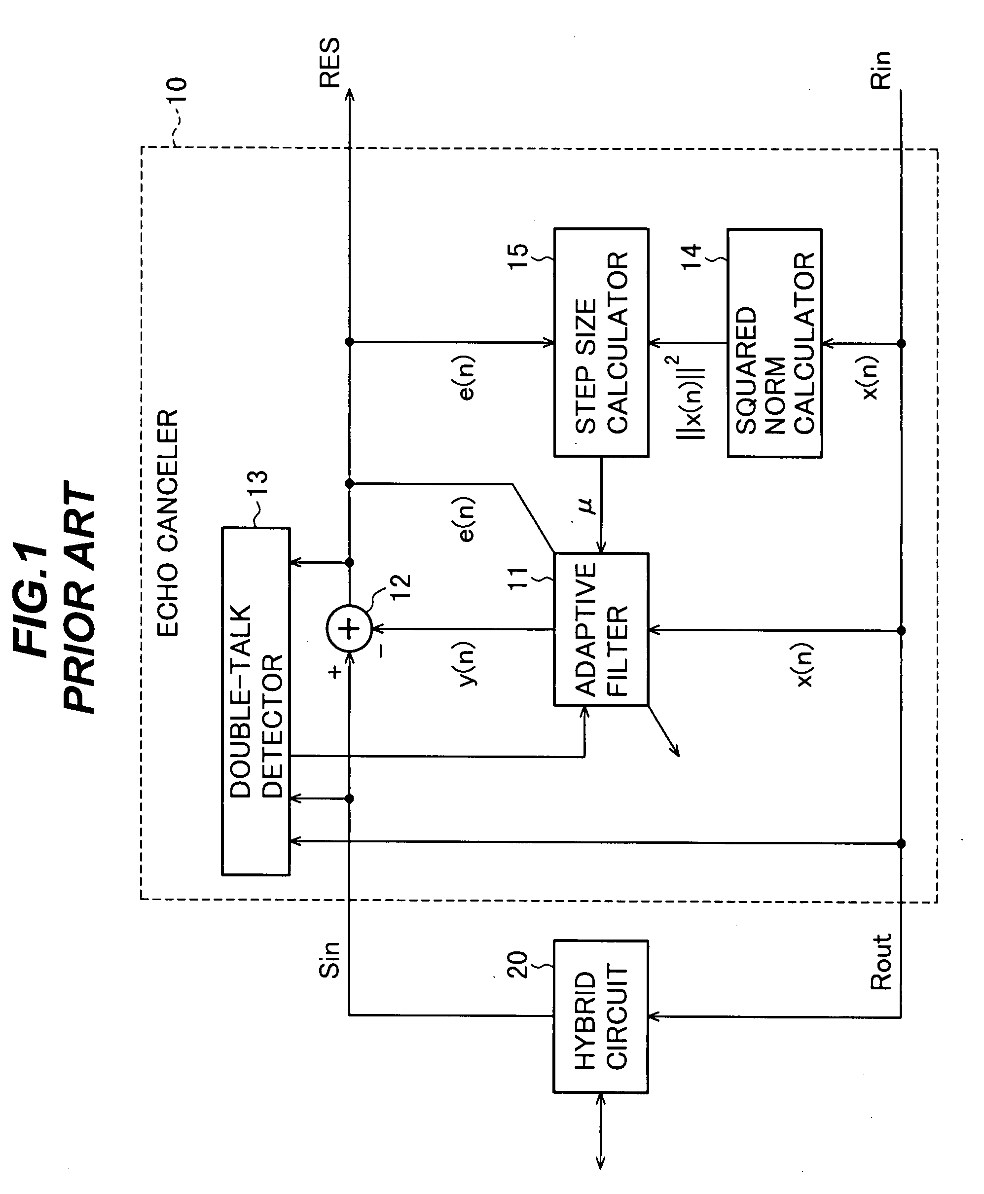
A problem with the conventional echo canceler described above is that the echo cancellation performance is significantly degraded in environments with much near-end background noise.
When the adaptive filter 11 updates its coefficients, this background noise interferes so that the filter coefficients do not converge as expected, making the echo replica signal an inaccurate replica of the true line echo.
The echo canceling performance in an environment with much background noise can be improved by reducing the step size parameter α and increasing the constant β, but this method has the drawback of reducing the speed of convergence in an environment with little background noise.

Method used


Image

  • Echo canceler and echo canceling method
  • Echo canceler and echo canceling method
  • Echo canceler and echo canceling method

Examples


first embodiment

[0058]Referring to FIG. 6, the echo canceler 100 in the first embodiment comprises at least an adaptive filter 11, a subtractor 12, a double-talk detector 13, a background noise estimator 110, a power calculator 140, and a step size calculator 150. This echo canceler 100 is obtained by adding the background noise estimator 110 to the conventional echo canceler shown in FIG. 1, replacing the squared norm calculator with the power calculator 140, and altering the operation of the step size calculator.

[0059]The adaptive filter 11 receives a step size μ from the step size calculator 150, performs the calculations in the modified normalized LMS coefficient updating formula given in the background, using the received step size μ, to update the filter coefficients, calculates the echo replica signal y(n) by the formula given in the background, and supplies the echo replica signal y(n) to the subtrahend input terminal of the subtractor 12.

[0060]The subtractor 12 subtracts the echo replica s...

second embodiment

[0092]The echo canceler and echo canceling method in the second embodiment of the invention will now be described with reference to the drawings.

[0093]The echo canceler according to the second embodiment is obtained from the echo canceler 100 according to the first embodiment in FIG. 6 by replacing the background noise estimator 110 shown in FIG. 7 with the background noise estimator 210 shown in FIG. 13.

[0094]The internal structure of the background noise estimator 210 in FIG. 13 will be described below. The other parts are the same as in FIG. 6.

[0095]Referring to FIG. 13, the background noise estimator 210 comprises an amplitude limiter 217, a multiplier 111, and an averager 112. As in the first embodiment, the averager 112 is, for example, an infinite impulse response (IIR) low pass filter (LPF) including multipliers 113, 116, an adder 114, and a delay element 115.

[0096]The amplitude limiter 217 pre-processes the residual error signal RES before it is squared, by limiting the amp...


PUM


Abstract

An echo canceler has an adaptive filter that generates an echo replica signal from a far-end signal. The filter coefficients of the adaptive filter are updated according to a residual error signal, which is obtained by subtracting the echo replica signal from a near-end signal to cancel echo. A background noise estimator estimates the near-end background noise power level from the residual error signal. A step size calculator uses the estimated near-end background noise power in determining the step size of the adaptive updating of the filter coefficients. When the estimated near-end background noise level is high, a small step size is used, which improves echo cancellation under these conditions. When the estimated near-end background noise level is low, a larger step size is used to permit rapid convergence of the filter coefficients.

Description

BACKGROUND OF THE INVENTION[0001]1. Field of the Invention[0002]The present invention relates to an echo canceler and echo canceling method useful, for example, for canceling line echo arising from a hybrid circuit in a telephone circuit.[0003]2. Description of the Related Art[0004]Referring to FIG. 1, a conventional echo canceler 10 of this type comprises an adaptive filter 11, a subtractor 12 (depicted as an adder with a negative subtrahend input terminal), a double-talk detector 13, a squared norm calculator 14, and a step size calculator 15.[0005]The echo canceler 10 receives a far-end input signal Rin from the party at the far end of the telephone connection. This far-end input signal Rin is furnished to the party at the near end of the connection as a far-end output signal Rout, and is furnished to the adaptive filter 11 as a digital far-end signal x(n).[0006]The adaptive filter 11 uses a set of filter coefficients to filter the far-end signal x(n) (which is identical to Rin),...

Claims


Application Information

Patent Timeline
Patent Type & Authority Applications(United States)
IPC IPC(8): H04M9/08
CPCH04B3/234
Inventor ISHIGURO, TAKASHIKIHARA, KOICHIMASUYA, YUZURUARAI, JUNJI
Owner OKI ELECTRIC IND CO LTD
Learn More