Surface covering panel

a technology for surface coverings and panels, applied in the direction of flooring, transportation and packaging, coatings, etc., can solve the problems of limited design flexibility, time-consuming and labor-intensive development of new surface textures, and small production runs that are impractical using this method

Inactive Publication Date: 2008-07-24
CHEN HAO A +1
View PDF15 Cites 88 Cited by
  • Summary
  • Abstract
  • Description
  • Claims
  • Application Information

AI Technical Summary

Benefits of technology

[0011]A further feature of the present invention is to provide a sharper, deeper, more defined and detailed textured design.
[0012]A further feature of the present invention is to provide a sophisticated and delicate design, such as a mosaic with multiple colors, shades, and sizes which can include wood knots, distressed wood, and other variations found in natural surface products.

Problems solved by technology

Along with the cost of such operations, it has been found that development of new surface textures is time consuming, taking up to six months in the engraving of the pressing plate, the determination of proper paper specifications regarding dimensional stability during printing and saturation, and the development of printing rolls so that the final print design after being impregnated will be in register with the engraved press plate.
Small production runs are impractical using this method.
The inflexibility of this method of producing floor covering also leads to limited design flexibility such as number of colors available to be used in printing, the pattern repeat length, and printing resolution of the gravure printing process.
Even if the above issues can be resolved, the registration tolerance of the finished product is so small that if the proper conditions during any of the preliminary steps is not properly maintained with accurate machine controls and operator attention, the print of the final product will not be aligned in register with the embossed regions of the plate.
This not only produces a visual aberration but will make it impossible to cut the boards later in an assembly line fashion.

Method used


Image

  • Surface covering panel
  • Surface covering panel
  • Surface covering panel

Examples


Embodiment Construction

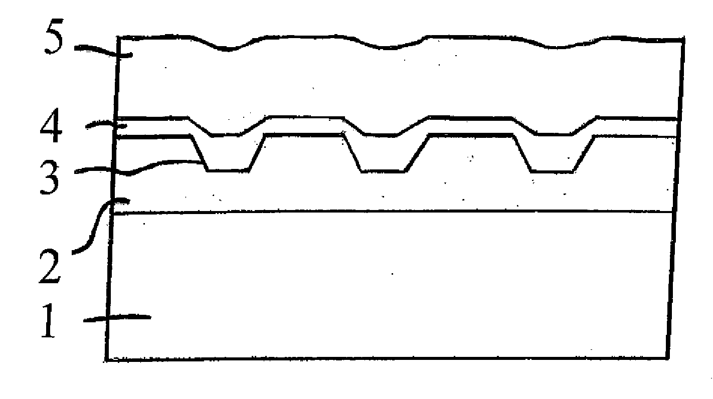
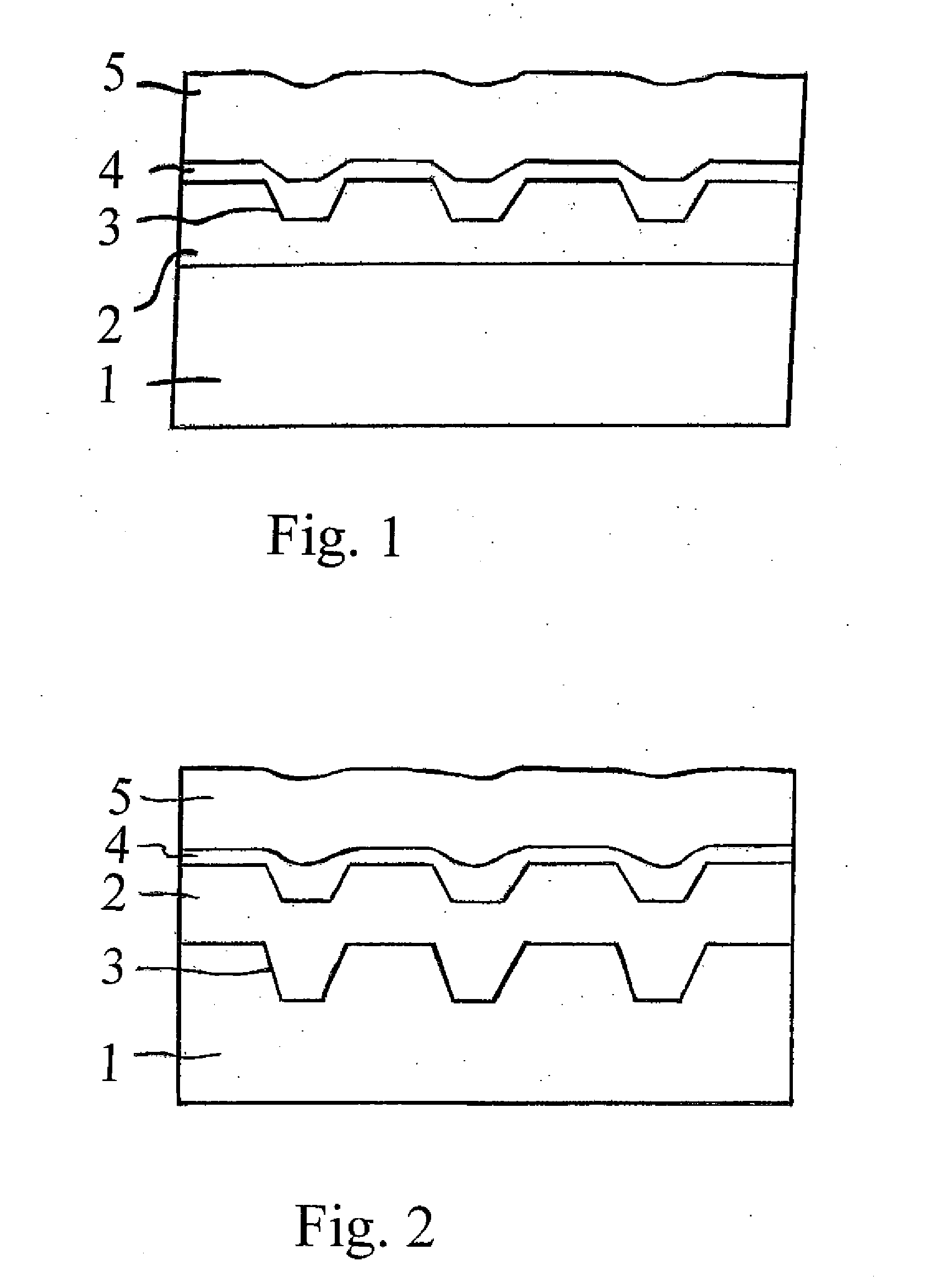
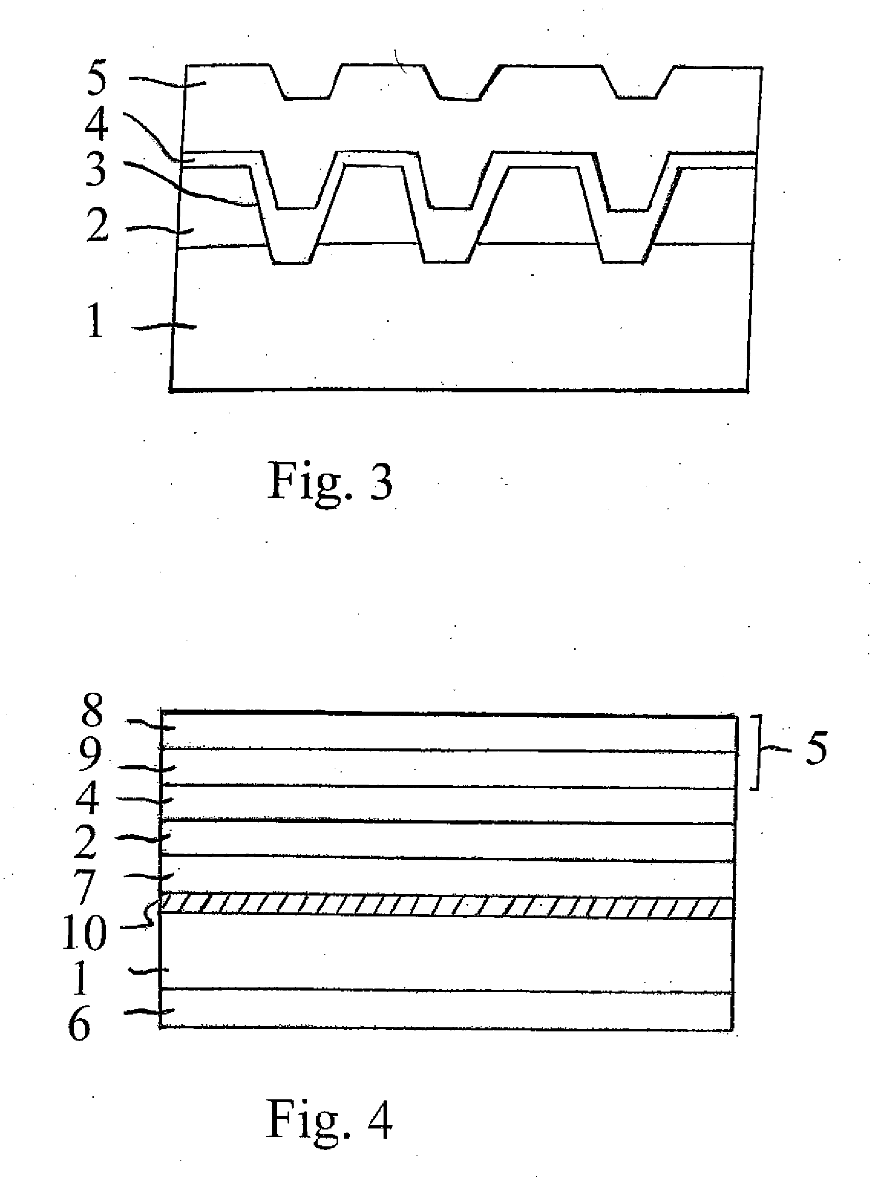
[0020]In general, surface coverings and methods of making the same are provided by the present invention. The surface coverings of the present invention provide, in the preferred embodiment, a surface covering panel having a natural appearance, for instance, a hard wood surface appearance and thus provides surface coverings that have a realistic appearance as compared to other types of non-natural surface coverings. The surface covering panels of the present invention also, or in the alternative, in a preferred embodiment, have a surface texture which is in register with a printed pattern or design. For purposes of the present invention, surface covering includes, but is not limited to, flooring, such as modular tiles, in-laid floors, solid vinyl floors, resilient floors, homogeneous floors, cushioned floors, and the like; wallpaper, laminates, countertops, and other surfaces decorated by consumers. In a preferred embodiment, the surface covering panel is quite useful with laminate-...


PUM

PropertyMeasurementUnit
thicknessaaaaaaaaaa
depthaaaaaaaaaa
depthaaaaaaaaaa

Abstract

A surface covering is described wherein the surface covering includes at least one support surface, such as a core, with at least one base coating located on the support surface. The support surface preferably has a textured top surface. A printed pattern is located on the base coating and preferably the printed pattern is in register with the textured surface. At least one protective layer is located on the printed pattern. Methods of making the surface covering are further described.

Description

[0001]This application claims the benefit under 35 U.S.C. §119(e) of prior U.S. Provisional Patent Application No. 60 / 423,096 filed Nov. 1, 2002, which is incorporated in its entirety by reference herein.BACKGROUND OF THE INVENTION[0002]The present invention relates to surface covering products, such as floor products, and methods of making the same. More particularly, the present invention relates to surface covering products which provide a unique appearance, such as highly detailed printed patterns on a textured surface.[0003]There is a continuing effort in the surface covering industry to provide surface covering products, such as floor covering products, that have a more realistic appearance to better compete with other floor covering products that are available to consumers, such as ceramic, wood, stone, brick, marble, textile weave, and granite flooring, and the like. Various efforts have been made, such as those described in U.S. Pat. No. 6,114,008 and U.S. Pat. No. 5,961,90...

Claims


Application Information

Patent Timeline
Patent Type & Authority Applications(United States)
IPC IPC(8): D06N7/04B05D3/00B05D5/00B05D5/06B05D7/00B41M7/00B44C5/04E04F13/08E04F13/16E04F13/18E04F15/02E04F15/04
CPCB05D5/061Y10T428/24364B05D7/57B32B38/06B41M5/0047B41M5/0064B41M7/0027B44C5/0446B44C5/0461E04F13/0871E04F13/16E04F13/18E04F15/02E04F15/02161Y10T428/16Y10T428/24562B05D7/53E04F13/165
Inventor CHEN, HAO A.EASTERDAY, NATHAN W.
Owner CHEN HAO A
Why Eureka
Try Eureka