
Device for enhancing fuel efficiency of internal combustion engines

a technology for internal combustion engines and fuel efficiency, applied in the direction of combustion-air/fuel-air treatment, combustible gas chemical modification, combustion-air/fuel-air treatment, etc., can solve the problems of complex fins and blades, green however does not disclose any structure, and the valve itself acts as an obstruction to air flow, so as to improve the fuel efficiency of an internal combustion engine and enhance the mixing of air

Inactive Publication Date: 2008-07-31
GLOBAL SUSTAINABILITY TECH
View PDF11 Cites 6 Cited by
  • Summary
  • Abstract
  • Description
  • Claims
  • Application Information

AI Technical Summary

Benefits of technology

[0011]Accordingly, it is an aspect of the present invention to provide a device that can be placed in the air and / or fuel flow path to enhance mixing of the air and fuel, to provide better fuel efficiency of an internal combustion engine, and / or an engine utilizing such device.

Problems solved by technology

But the valve itself acts as an obstruction to air flow even when fully open.
Green however does not disclose any structure to promote better mixing of the resulting mixture.
Reissmuller however requires a complex fins and blades, which are difficult to fabricate.
Unfortunately, these devices provide less than satisfactory results.

Method used


Image

  • Device for enhancing fuel efficiency of internal combustion engines
  • Device for enhancing fuel efficiency of internal combustion engines
  • Device for enhancing fuel efficiency of internal combustion engines

Examples


Embodiment Construction

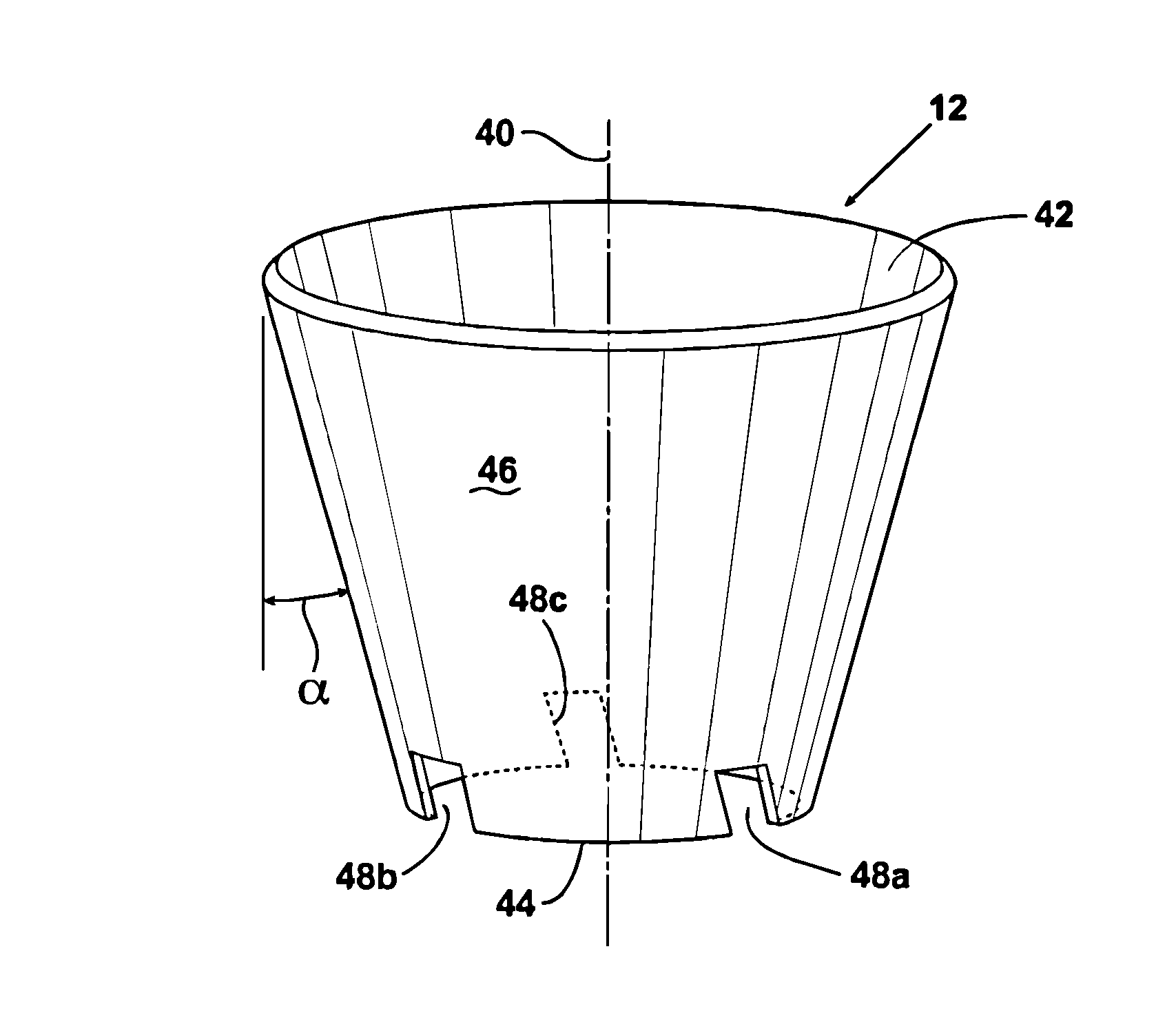
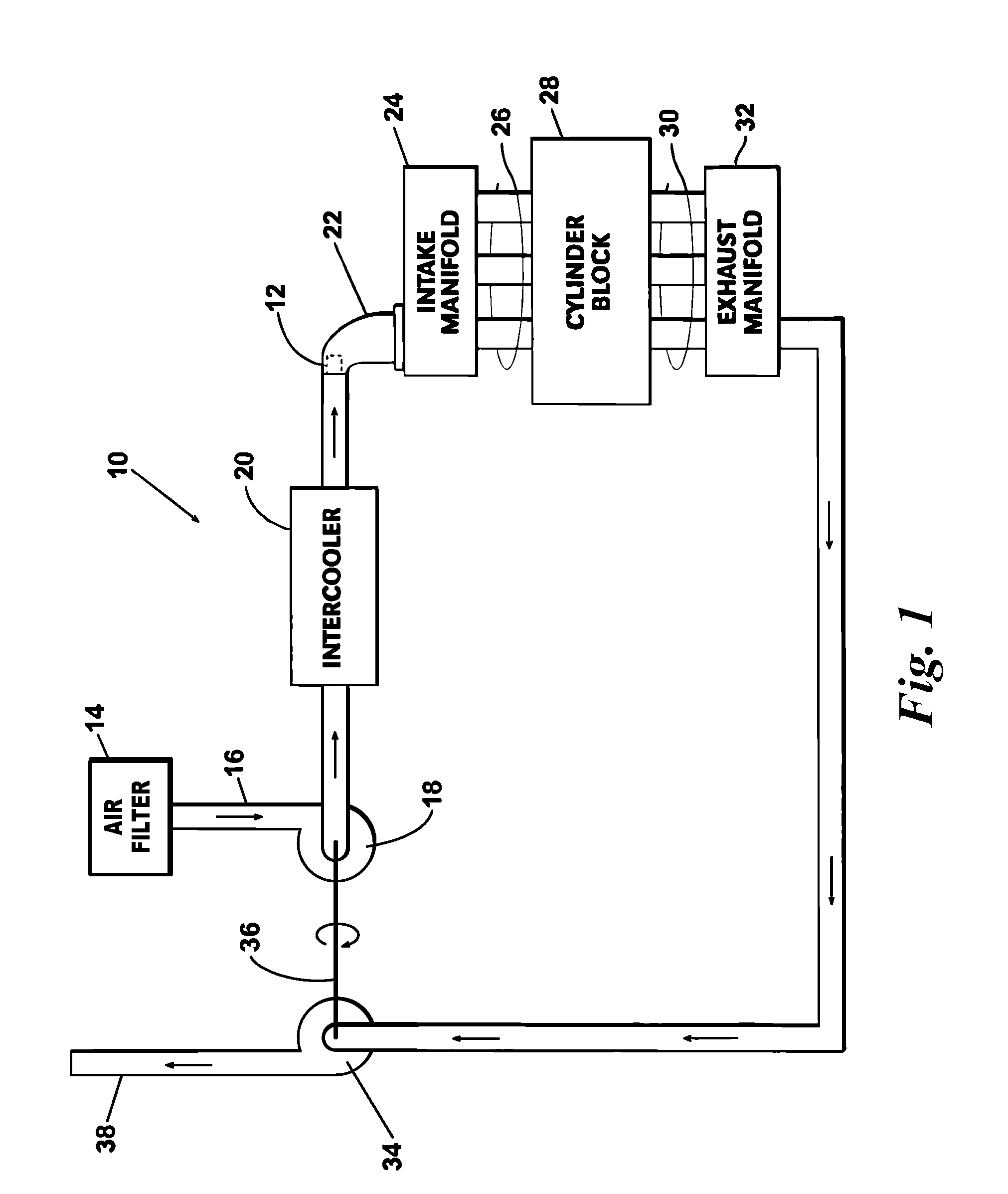
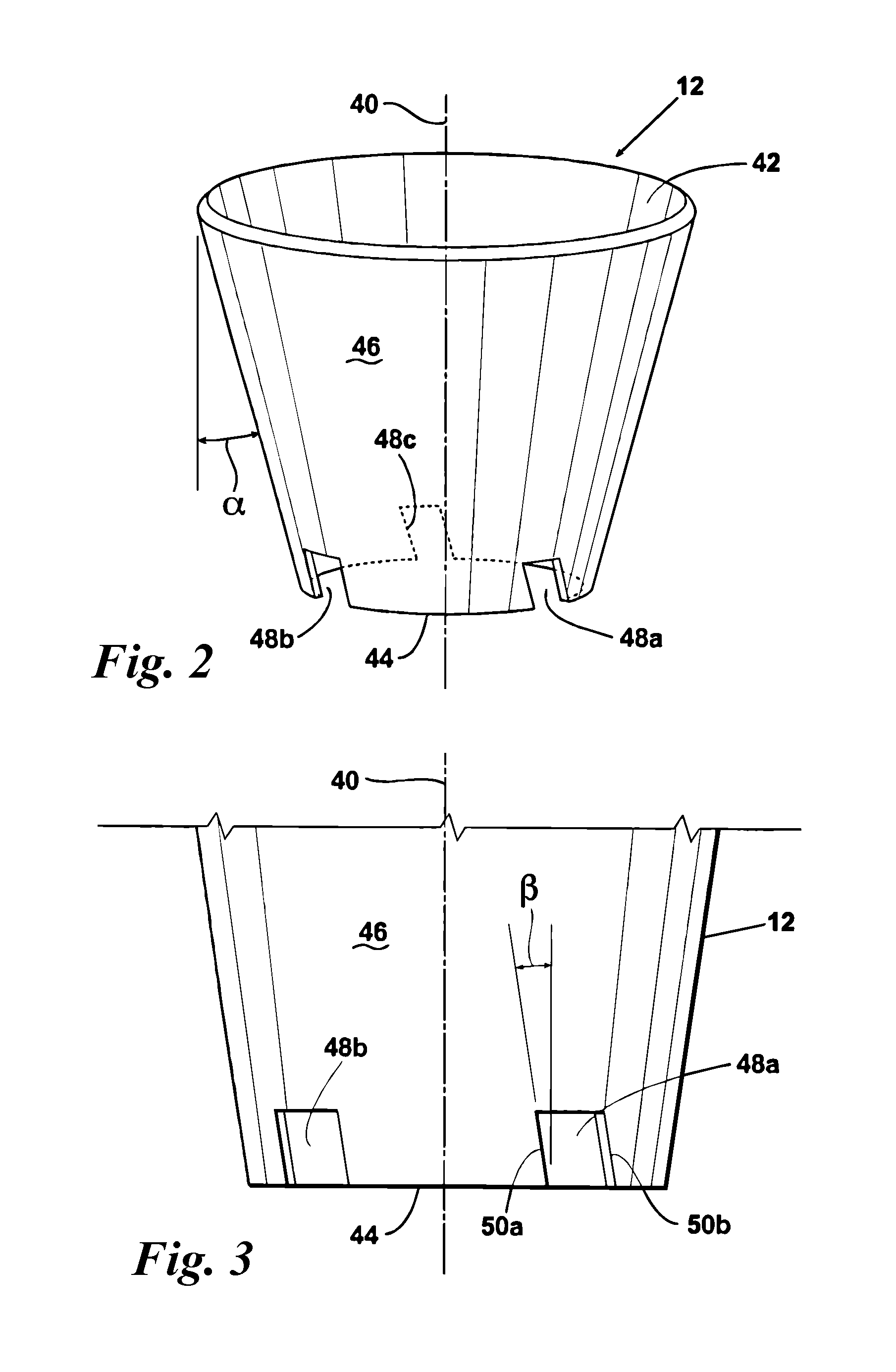
[0049]Turning now to the drawings wherein like reference characters indicate like or similar parts throughout, FIG. 1 illustrates a typical turbo-charged diesel engine 10 having installed therein a fuel efficiency enhancement device, or gas flow conditioner 12, for enhancing the flow of gas in an IC engine having an air intake system and an exhaust system. The conditioner is sized to fit inside a duct or other passageway for intake air, a fuel-air mixture, or exhaust. Although FIG. 1 illustrates a particular type of IC engine (i.e., a turbocharged diesel engine), it will be understood that the invention may be employed in other engine types, including spark ignition engines with or without turbo charging, with or without fuel injection, etc. Additionally, while FIG. 1 shows a particular placement of the gas flow conditioner 12, it will be understood that the conditioner 12 can be advantageously positioned at other areas of the engine, as further explained below.

[0050]Intake air for ...


PUM


Abstract

An air / fuel flow structure for enhancing the fuel efficiency of an internal combustion engine includes a generally conical-shaped flow path useable in the engine. One or more tab and one or more notch are formed in the conical path to alter one or more characteristics, such as pressure and velocity, of the gas flow. The apparatus may be positioned in the air intake system. Alternatively, the apparatus may be positioned in the exhaust system.

Description

REFERENCE TO RELATED APPLICATIONS[0001]This is a continuation-in-part of U.S. application Ser. No. 11 / 520,372, filed Sep. 13, 2006, which in turn claims priority to U.S. Provisional Patent Application No. 60 / 749,576, filed Dec. 12, 2005, the disclosures of both of which are incorporated herein by reference.FIELD OF THE INVENTION[0002]The present invention relates to a device for enhancing the fuel efficiency of internal combustion engines.BACKGROUND OF THE INVENTION[0003]The fuel efficiency of an internal combustion (IC) engine depends on many factors. One of these factors is the extent to which the fuel is mixed with air prior to combustion. Another factor that affects fuel efficiency is the amount of air that can be moved through the engine. Backpressure in the exhaust system restricts the amount of air that can be input to the engine. Additionally, most IC engines of the spark ignition type employ a so-called “butterfly” valve for throttling air into the engine. But the valve its...

Claims


Application Information

Patent Timeline
Patent Type & Authority Applications(United States)
IPC IPC(8): F02M29/14
CPCB01F5/061B01F5/0646B01F5/0651B01F2005/0621B01F2005/0636F02M29/06F01N2240/20F01N2240/36F02B29/0425F02B37/00F02D9/104F01N13/10B01F25/4317B01F25/431971B01F25/4334B01F25/433
Inventor RUSSELL, RAYMOND B.
Owner GLOBAL SUSTAINABILITY TECH
Learn More