Rotary drag bit

a rotary drag bit and cutting element technology, applied in earth drilling, drilling accessories, construction, etc., can solve the problems of shortened life of rotary drag bits using such cutting elements, shortened cutting life wear of cutting elements of rotary drag bits, so as to prolong cutter life, reduce stress on cutters, and improve cutting efficiency.

Active Publication Date: 2008-07-31
BAKER HUGHES INC
View PDF63 Cites 40 Cited by
  • Summary
  • Abstract
  • Description
  • Claims
  • Application Information

AI Technical Summary

Benefits of technology

[0012]Accordingly, embodiments of a rotary drag bit include a primary cutter row comprising at least one primary cutter and a multiple backup cutter group comprising a first and second trailing cutter rows, each comprising at least one cutter positioned to follow the at least one primary cutter is provided. The rotary drag bit life is extended by the multiple backup cutter group, making the bit more durable and extending the life of the cutters. Further, the cutters of the multiple backup cutter group are configured to selectively engage and fracture a subterranean formation material being drilled, providing improved bit life and reduced stress upon the cutters.

Problems solved by technology

While the PDC cutting element improves drill hit efficiency in drilling many subterranean formations, the PDC cutting element is nonetheless prone to wear when exposed to certain drilling conditions, resulting in a shortened life of a rotary drag bit using such cutting elements.
The decrease in the penetration rate is a manifestation that the cutting elements of the rotary drag bit are wearing out, particularly when other drilling parameters remain constant.
While researchers continue to develop and seek out improvements for longer lasting cutters or generalized improvements to cutter performance, they fail to accommodate or implement an engineered approach to achieving longer drag bit life by maintaining or increasing ROP by taking advantage of cutting element wear rates.
The use of backup cutters has proven to be a convenient technique for extending the life of a bit, while enhancing stability without the necessity of designing the bit with additional blades to carry more cutters which might resultantly decrease ROP and which potentially compromises bit hydraulics due to reduced available fluid flow area over the bit face and less-than-optimum fluid flow due to unfavorable placement of nozzles in the bit face.
Also, it is believed that conventional backup cutters in combination with their associated primary cutters may undesirably lead to balling of the blade area with formation material.
Conventional wisdom is that providing backup cutters may cause the blade of the bit to ball with formation material because of either reduced flow area or because of physical limitations associated with each blade, even though the backup cutters may increase the life and overall performance to the drag bit.

Method used


Image

  • Rotary drag bit
  • Rotary drag bit
  • Rotary drag bit

Examples


first embodiment

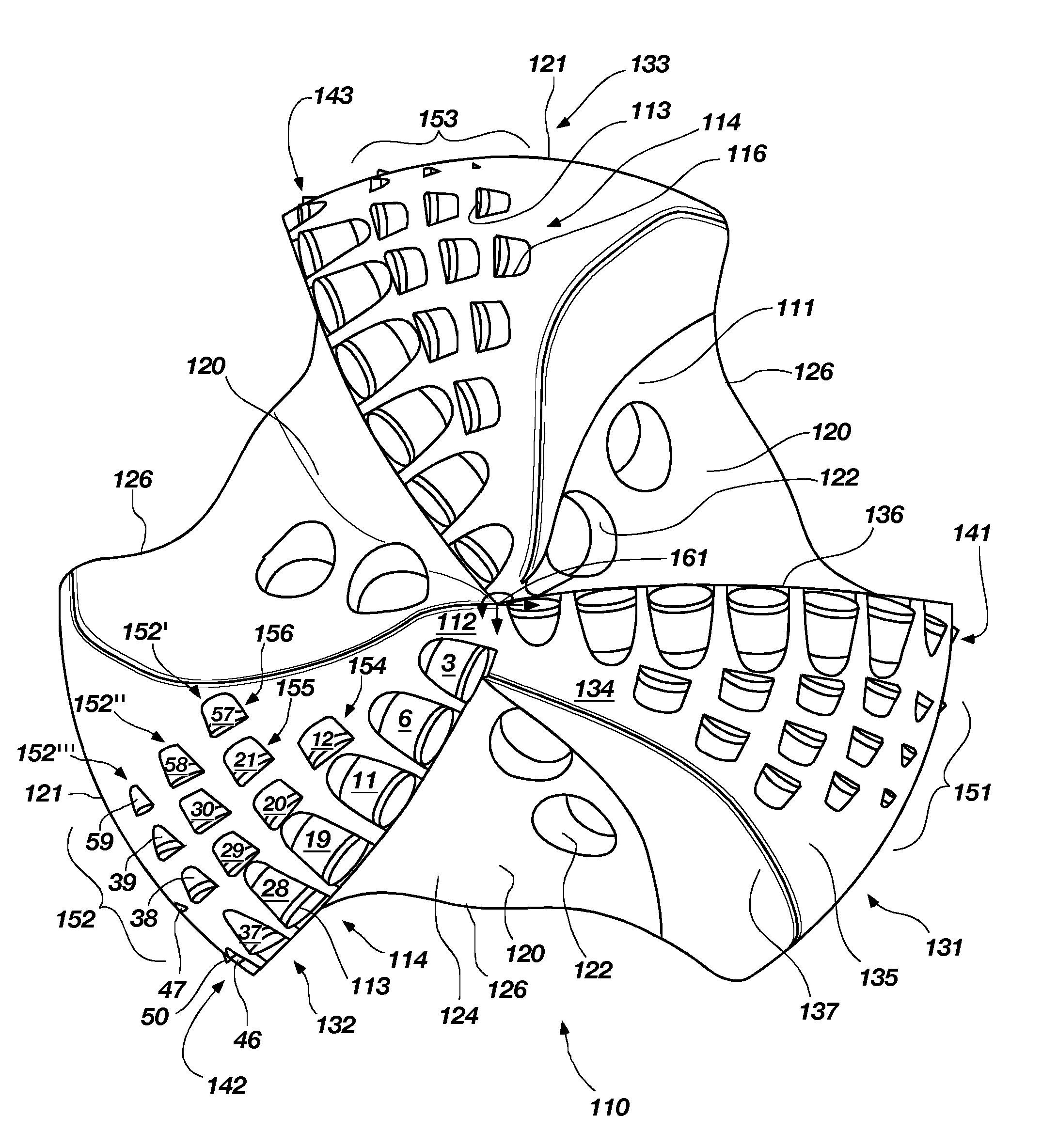
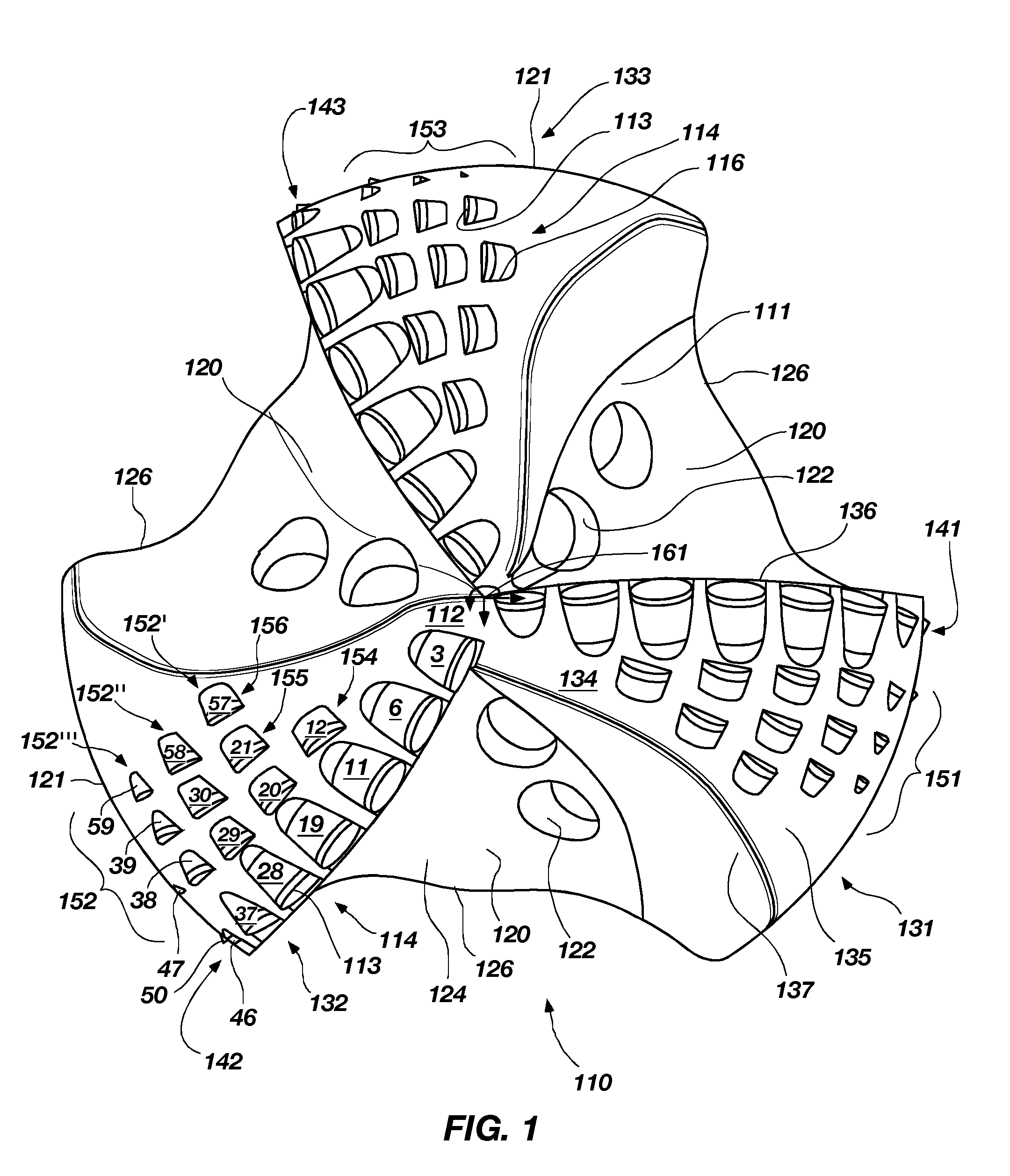
[0060]FIG. 1 shows a frontal view of a rotary drag bit 110 in accordance with the invention. The rotary drag bit 110 comprises three blades 131, 132, 133, three primary cutter rows 141, 142, 143 and three multiple backup cutter groups 151, 152, 153, respectively. While three multiple backup cutter groups 151, 152, 153 are included, it is contemplated that the drag bit 110 may include one multiple backup cutter group on one of the blades or a plurality of backup cutter groups on the blades greater or less than the three illustrated. Further, it is contemplated that the drag bit 110 may have more or less blades than the three illustrated. Each of the multiple backup cutter groups 151, 152, 153 may have one or more multiple backup cutter sets. For example, without limitation, the multiple backup cutter group 152 includes three multiple backup cutter sets 152′, 152″, 152′″. Before turning to a detailed description of multiple backup cutter sets 152′, 152″, 152′″ of the multiple backup c...

second embodiment

[0083]FIG. 5 shows a frontal view of a rotary drag bit 210 in accordance with the invention. The rotary drag bit 210 comprises six blades 231, 231′, 232, 232′, 233, 233′ each having a primary or first cutter row 241 and a backup or second cutter row 251 extending from the center line C / L of the bit 210. The cutter rows 241, 251 include cutters 214 coupled to cutter pockets 216 of the blades 231,231′, 232, 232′, 233, 233′. It is contemplated that each blade 231, 231′, 232, 232′, 233, 233′ may have more or less cutter rows 241, 251 than the two illustrated. Also, each of the cutter rows 241, 251 may have fewer or greater numbers of cutters 214 than illustrated on each of the blades 231, 231′, 232, 232′, 233, 233′. In this embodiment, blades 231, 232, 233 are primary blades and blades 231′, 232′, 233′ are secondary blades. The secondary blades 231′, 232′, 233′ provide support for adding additional cutters 214, particularly, in the nose region 262 (see FIG. 6) where the work requirement...

third embodiment

[0091]FIG. 13 shows a frontal view of a rotary drag bit 310 in accordance with the invention. The rotary drag bit 310 comprises three primary blades 331, 332, 333 each comprising a primary or first cutter row 341, 342, 343, a backup or second cutter row 344, 345, 346, and an additional backup or third cutter row 347, 348, 349, respectively, extending radially outward from the center line C / L of the bit 310. Optionally, one or more additional backup cutter rows may be provided upon at least one of the blades 331, 332, 333 beyond the first cutter rows 341, 342, 343 and the second cutter rows 344,345, 346 illustrated. The cutter rows 341, 342, 343, 344, 345, 346, 347, 348, 349 include a plurality of cutters 314; each cutter 314 coupled to a cutter pocket 316 of the blades 331, 332, 333.

[0092]The cutters 314 in cutter rows 341, 342, 343 are fully exposed cutters as shown in FIG. 14, which shows a cutter and blade profile 330 for the third embodiment of the invention. The drag bit 310 ha...


PUM


Abstract

A rotary drag bit includes a primary cutter row comprising at least one primary cutter and a multiple backup cutter group. The multiple backup cutter group comprises a first and second trailing cutter row, each comprising at least one cutter positioned to follow the at least one primary cutter. The rotary drag bit life is extended by the multiple backup cutter groups making the bit more durable and extending the life of the cutters. Further, the cutters of the multiple backup cutter group are configured to selectively engage a subterranean formation material being drilled, providing improved bit life and reduced stress upon the cutters. Other embodiments of rotary drag bits are provided.

Description

CROSS-REFERENCE TO RELATED APPLICATION[0001]This application claims the benefit of U.S. Provisional Patent Application Ser. No. 60 / 897,457 filed Jan. 25, 2007, for “ROTARY DRAG BIT,” the entire disclosure of which is hereby incorporated herein by this reference.TECHNICAL FIELD[0002]The present invention in several embodiments, relates generally to a rotary drag bit for drilling subterranean formations and, more particularly, to rotary drag bits having select cutter configurations in multiple groupings configured to enhance cutter life and performance. Further, the invention, in other embodiments, relates to a rotary drag bit having a relatively higher blade cutting structure count on a lower blade count bit.BACKGROUND[0003]Rotary drag bits have been use for subterranean drilling for many decades, and various sizes, shapes and patterns of natural and synthetic diamonds have been used on drag bit crowns as cutting elements. A drag bit can provide an improved rate of penetration (ROP) ...

Claims


Application Information

Patent Timeline
Patent Type & Authority Applications(United States)
IPC IPC(8): E21B10/43
CPCE21B10/55E21B10/43
Inventor GAVIA, DAVIDHANFORD, RYAN J.SNELL, LANE E.HOINES, JASON E.ISBELL, MATTHEW R.MCCLAIN, ERIC E.DOSTER, MICHAEL L.
Owner BAKER HUGHES INC
Why Eureka
Try Eureka