RFID Communication System and Method of Operation

a communication system and communication method technology, applied in multiplex communication, burglar alarm mechanical actuation, instruments, etc., can solve the problems of limited power which can be used for communicating data, drawbacks of amplitude modulation techniques, and only able to operate over a relatively short range of identification systems, so as to reduce the power within the carrier signal

Inactive Publication Date: 2008-07-31
ROUND ROCK RES LLC
View PDF36 Cites 30 Cited by
  • Summary
  • Abstract
  • Description
  • Claims
  • Application Information

AI Technical Summary

Benefits of technology

[0012]One aspect of the invention provides a backscatter interrogator. The backscatter interrogator includes a data path configured to communicate a data signal and a signal generator configured to generate a carrier signal. The carrier signal comprises a microwave signal in preferred embodiments. The interrogator also provides a modulator coupled with the data path and the signal generator. The modulator is configured to spread the data signal to define a spread data signal and amplitude modulate the carrier signal using the spread data signal. The modulator is further configured to phase modulate the carrier signal to reduce the power within the carrier signal.

Problems solved by technology

However, such identification systems are only capable of operation over a relatively short range, limited by the size of a magnetic field used to supply power to the devices and to communicate with the devices.
However, drawbacks exist with the utilization of amplitude modulation techniques.
This limits the power which can be used for communicating data if AM modulation and spread spectrum techniques are utilized within the above specified frequency band.

Method used


Image

  • RFID Communication System and Method of Operation
  • RFID Communication System and Method of Operation
  • RFID Communication System and Method of Operation

Examples


Embodiment Construction

[0028]This disclosure of the invention is submitted in furtherance of the constitutional purposes of the U.S. Patent Laws “to promote the progress of science and useful arts” (Article 1, Section 8).

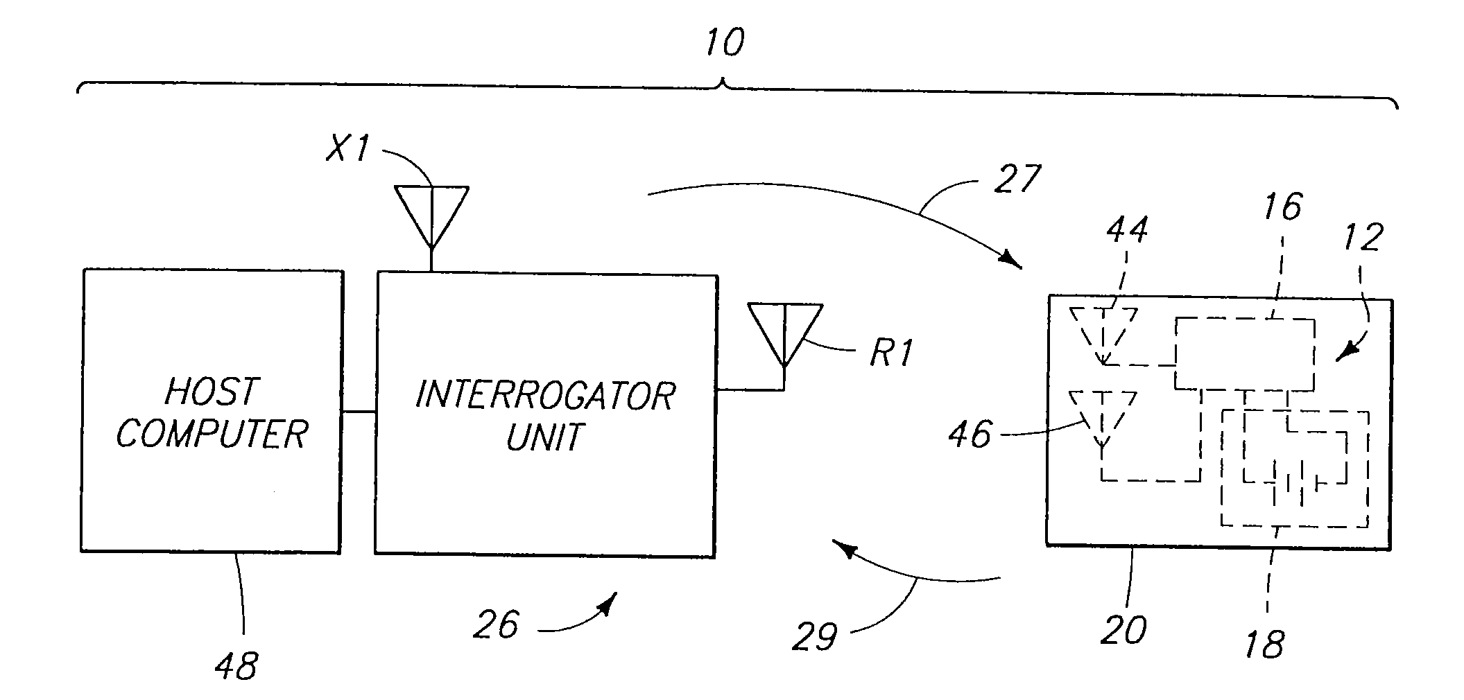
[0029]FIG. 1 illustrates a wireless communications system 10 embodying the invention. Communications system 10 includes a first transponder including an interrogator 26 and a host computer 48 in communication with interrogator 26. Communications system 10 further includes an electronic communications device 12, such as the device disclosed in U.S. patent application Ser. No. 08 / 705,043, filed Aug. 29, 1996. In one embodiment, wireless communications device 12 comprises a wireless identification device such as the Microstamp™ integrated circuit available from Micron Communications, Inc., 3176 S. Denver Way, Boise, Id. 83705. Interrogator 26 communicates with the communications device 12 via an electromagnetic link, such as via an RF link (e.g., at microwave frequencies, in one embodiment)....


PUM


Abstract

A radio frequency identification (RFID) system enabling backscatter communication between a reader and a tag. A baseband data signal is encoded, and it may be selectively inverted and used to modulate a carrier using amplitude modulation, phase modulation, or both amplitude and phase modulation. A reply received from the tag in response to a command from the reader may include an identification code associated with an object to which the tag is affixed.

Description

RELATED PATENT DATA[0001]This patent is a continuation of U.S. patent application Ser. No. 09 / 961,113, filed Sep. 20, 2001, entitled “Backscatter Interrogators, Communication Systems and Backscatter Communication Methods,” naming David K. Ovard and Roy Greeff as inventors, which is a continuation of U.S. patent application Ser. No. 09 / 066,610 (now U.S. Pat. No. 6,459,726), filed Apr. 24, 1998; the disclosures of which are incorporated herein by reference.TECHNICAL FIELD[0002]The present invention relates to backscatter interrogators, communication systems and backscatter communication methods.BACKGROUND OF THE INVENTION[0003]Backscatter communication systems are known in the art. In a backscatter system, one transponder, such as an interrogator, sends out a command to a remote communications device. After the interrogator transmits the command, and is expecting a response, the interrogator switches to a CW mode (continuous wave mode). In the continuous wave mode, the interrogator do...

Claims


Application Information

Patent Timeline
Patent Type & Authority Applications(United States)
IPC IPC(8): G06K7/00G08B13/14H04B7/22H04B1/707H04J13/00
CPCG06K7/0008H01Q1/2208G06K19/0723H04B7/22H04J13/0022H04B1/707G06K7/10366
Inventor OVARD, DAVID K.GREEFF, ROY
Owner ROUND ROCK RES LLC
Why Eureka
Try Eureka