Liquid discharging head and method for producing the liquid discharging head

a liquid channel and liquid technology, applied in the direction of printing, manufacturing tools, solvent processing, etc., can solve the problems of difficult to discharge the bubbles, the plate cannot be torn off after bonded, and the plate cannot be tripped off to correct the positional deviation, etc., to achieve easy smoothing of the inner surface of the liquid channel, and without adversely affecting the water repellent film

Inactive Publication Date: 2008-07-31
BROTHER KOGYO KK
View PDF1 Cites 10 Cited by
  • Summary
  • Abstract
  • Description
  • Claims
  • Application Information

AI Technical Summary

Benefits of technology

[0012]According to the liquid discharging head of the present invention, since, in the inner surface of the liquid channel, the curing material is filled in the step formed due to the shift of the openings of the adjacent plates among the plurality of plates, the curing material makes the channel inner surface smooth. Therefore, in the liquid channel, the attenuation of a pressure wave due to such a step occurs little and residual bubbles are reduced, resulting in excellent bubble discharging capability.
[0013]In the liquid discharging head of the present invention, the plurality of plates may be bonded by metal diffusion bonding. In this case, since the step in the inner surface of the liquid channel, that is, the step formed due to the shift of the openings of the adjacent plates bonded by the metal diffusion bonding is smoothed by the curing material, the attenuation of a pressure wave due to the step occurs little and residual bubbles are reduced, resulting in excellent bubble discharging capability.
[0014]In the liquid discharging head of the present invention, the liquid which is discharged from the nozzle may be an ink. In this case, the inner surface of the liquid channel (ink channel) in the liquid discharging head as an ink-jet head can be smoothed.
[0018]According to the method for producing the liquid discharging head of the present invention, when the plates are stacked by metal diffusion bonding to form the liquid channel, it is possible to smooth a step formed in a channel inner surface by the curing material. At this time, gaps, flaws, and recesses can also be smoothed by the curing material. Therefore, the attenuation of a pressure wave due to the step of the liquid channel occurs little, and residual bubbles are reduced, which makes it possible to produce the liquid discharging head excellent in bubble discharging capability.
[0020]In the method for producing the liquid discharging head of the present invention, the curing material may be a thermosetting adhesive, and the fluid may be a high-temperature air. Further, a temperature of the high-temperature air may be about 70° C. to about 150° C. This makes it possible to introduce the thermosetting adhesive throughout the liquid channel and thereafter dry the thermosetting adhesive by the high-temperature air. Therefore, the thermosetting adhesive can form part of the inner surface of the liquid channel, which makes it possible to easily smooth the inner surface of the liquid channel.
[0021]In the method for producing the liquid discharging head of the present invention, the plates may include a nozzle plate stacked on an outermost side of the channel unit; other plates among the plurality of plates which are different from the nozzle plate may be bonded to form a stack in the first step; and the method may further include, after the third step, a fourth step for bonding the nozzle plate to the stack. Further, the nozzle plate may be bonded to the stack in the fourth step by an adhesive. This makes it possible to easily smooth the inner surface of the liquid channel without adversely affecting a water repellent film even in a case where the water repellent film is formed on the nozzle plate. Further, the channel can be free of steps formed due to the shift of the openings of the adjacent plates and thus the liquid can smoothly flow in the channel.

Problems solved by technology

However, in a case where metal diffusion bonding is used to form the channel unit, the plates cannot be torn off after bonded.
Therefore, even if steps and gaps occur in liquid channels due to, for example, positional deviation or shift of openings formed in the plates, it is not possible to tear off the plates to correct the positional deviation or shift.
Further, it is difficult to discharge these bubbles even by purging.
Further, if steps and gaps occur in descenders each of which communicates a nozzle and a pressure chamber for applying jetting pressure to the liquid, a pressure wave attenuates, resulting in low driving efficiency of an actuator.
Thus, the head formed by metal diffusion bonding has problems that bubbles easily stay in the steps and the gaps occurring in the liquid channels and the bubbles prevent stable discharge of the liquid.
Another problem is that the pressure wave attenuates due to the steps and the gaps, resulting in low driving efficiency of the actuator.
Therefore, this method is not applicable to steps which occur after a plurality of plates are bonded by, for example, metal diffusion bonding or the like, as a result of shift or positional deviation of openings formed in the plates.

Method used


Image

  • Liquid discharging head and method for producing the liquid discharging head
  • Liquid discharging head and method for producing the liquid discharging head
  • Liquid discharging head and method for producing the liquid discharging head

Examples


Embodiment Construction

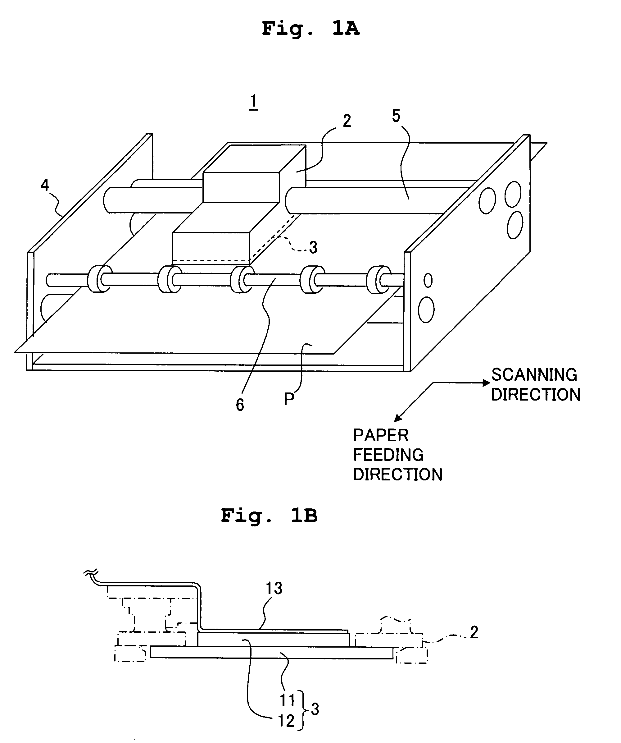
[0037]Hereinafter, an embodiment where the present invention is applied to an ink-jet printer head will be explained with reference to the drawings. FIG. 1A is shows a perspective view illustrating the structure of an ink-jet printer according to the present invention, and FIG. 1B is an explanatory view showing the arrangement relation of a channel unit, an actuator unit, and a flexible cable (COP) according to the present invention.

[0038]As shown in FIG. 1A, the ink-jet printer 1 according to the present invention includes a carriage 2 on which an ink cartridge (not shown) is mounted, and an ink-jet printer head 3 (hereinafter, simply referred to as a printer head) provided on a lower surface of the carriage 2 to perform recording to a recording paper P (recording medium). The carriage 2 is supported by a carriage shaft 5 and a guide plate (not shown) which are provided in a printer frame 4, and reciprocates in a scanning direction perpendicular to a paper feeding direction of the ...


PUM

PropertyMeasurementUnit
temperatureaaaaaaaaaa
piezoelectricaaaaaaaaaa

Abstract

A liquid discharging head includes a channel unit formed of a plurality of stacked plates having openings and a liquid channel formed of the openings of the stacked plates. A curing material is filled in a step formed due to shift of the openings provided in the adjacent plates respectively, and the curing material forms part of an inner surface of the liquid channel. Consequently, the channel inner surface becomes smooth, and a liquid discharging head with little residual bubbles and with excellent bubble discharging capability is provided. Further, the attenuation of a pressure wave due to the step can be prevented.

Description

CROSS REFERENCE TO RELATED APPLICATION[0001]The present application claims priority from Japanese Patent Application No. 2006-258302, filed on Sep. 25, 2006, the disclosure of which is incorporated herein by reference in its entirety.BACKGROUND OF THE INVENTION[0002]1. Field of the Invention[0003]The present invention relates to a liquid discharging head and a method for producing the liquid discharging head.[0004]2. Description of the Related Art[0005]There has been known a liquid discharging head formed of a plurality of stacked plates, having liquid channels which are formed by making openings formed in the respective plates communicate with one another, and discharging, from nozzles, a liquid flowing through the liquid channels.[0006]In recent years, as the specifications of a liquid discharging head have become diversified, its producing methods have also become diversified. For example, the use of metal diffusion bonding for bonding plates to form a channel unit has an advanta...

Claims


Application Information

Patent Timeline
Patent Type & Authority Applications(United States)
IPC IPC(8): B41J2/01
CPCB41J2/14233B41J2/161B41J2/1623B41J2/1626B41J2002/14475B41J2002/14306B41J2002/14419B41J2002/14459B41J2/1634
Inventor KATAYAMA, NAOKI
Owner BROTHER KOGYO KK
Why Eureka
Try Eureka