Eureka AIR delivers breakthrough ideas for toughest innovation challenges, trusted by R&D personnel around the world.

Method and system for communication channel characterization

Active Publication Date: 2008-07-31
RAYTHEON CO
View PDF4 Cites 11 Cited by
  • Summary
  • Abstract
  • Description
  • Claims
  • Application Information

AI Technical Summary

Benefits of technology

[0025]The present invention provides a channel characterization system and method that can identify communication channel characteristics (i.e., magnitude and phase response) with minimum loss of channel bandwidth, and which can be used to identify channel characteristics for a channel with dynamically changing characteristics. The identified channel characteristic can be used to dynamically adjust a receiver to compensate for the identified channel characteristics.

Problems solved by technology

It is known that transmission of a digital signal through a medium, whether wired or wireless, can result in the digital signal becoming distorted due to affects of the medium.
Digital signals transmitted though a wireless medium (i.e., wireless signals) can be distorted due to effects of multipath fading, magnitude response, and phase response of the wireless medium.
Digital signals transmitted though a wire medium (i.e., wired signals) can also be distorted due to effects of magnitude response and phase response of the wired medium.
Distortion of a digital signal can lead to loss of data, or data that is not properly interpreted by a receiver of the digital signal.
To be successful, however, most of these methods require prior knowledge of the medium fading and attenuation characteristics.
A disadvantage of using pilot tones is that the pilot tones carry no data.
Therefore, use of the pilot tones results in a loss of channel bandwidth that could otherwise be used for data transmission.
A ship, and especially a military ship, represents a unique and particularly challenging environment in which a wireless signal must propagate through a communication channel comprised of Faraday cages, i.e., all-metal compartments.
Furthermore, reflective surfaces within the compartments are subject to movement.
However, most of these methods require prior knowledge of channel characteristics to optimally reconstruct and decode the received signal.
This can be an issue in situations where channel characteristics are changing rapidly.
Computational complexity increases from correlation to BLUE to MMSE.
Correlation is the most computationally straightforward of the three methods, but it is also the most sensitive to noise.
This approach is more computationally intensive than correlation, in that a matrix, which incorporates the pilot data, must be inverted.
Therefore, SOCS may not be applicable to systems that are changing rapidly, and in general, HOS will not be readily applicable to MIMO (Multiple Input / Multiple Output) channels that have been Space-Time coded, because the coded signals are not statistically independent.

Method used


Image

  • Method and system for communication channel characterization
  • Method and system for communication channel characterization
  • Method and system for communication channel characterization

Examples


Embodiment Construction

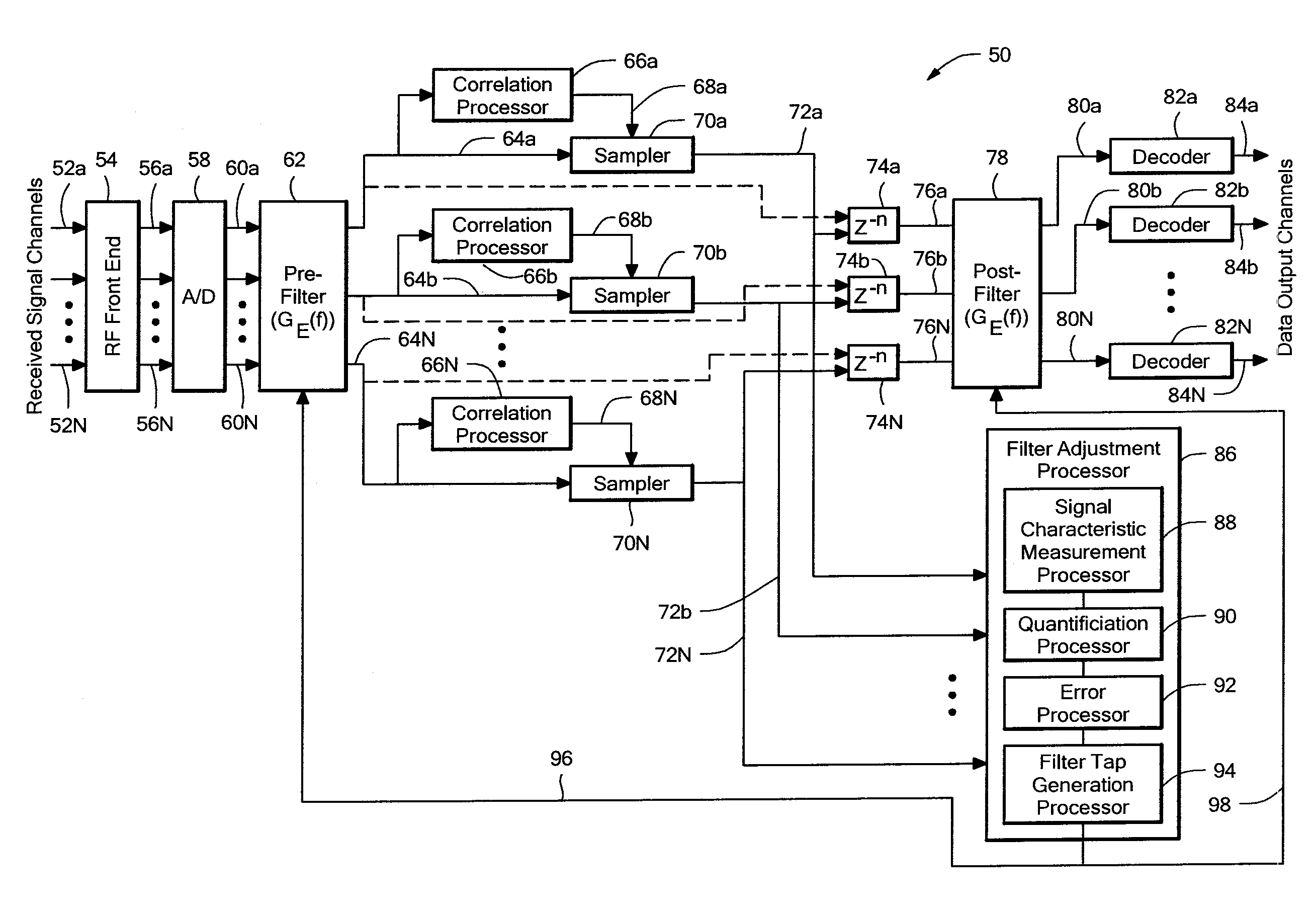
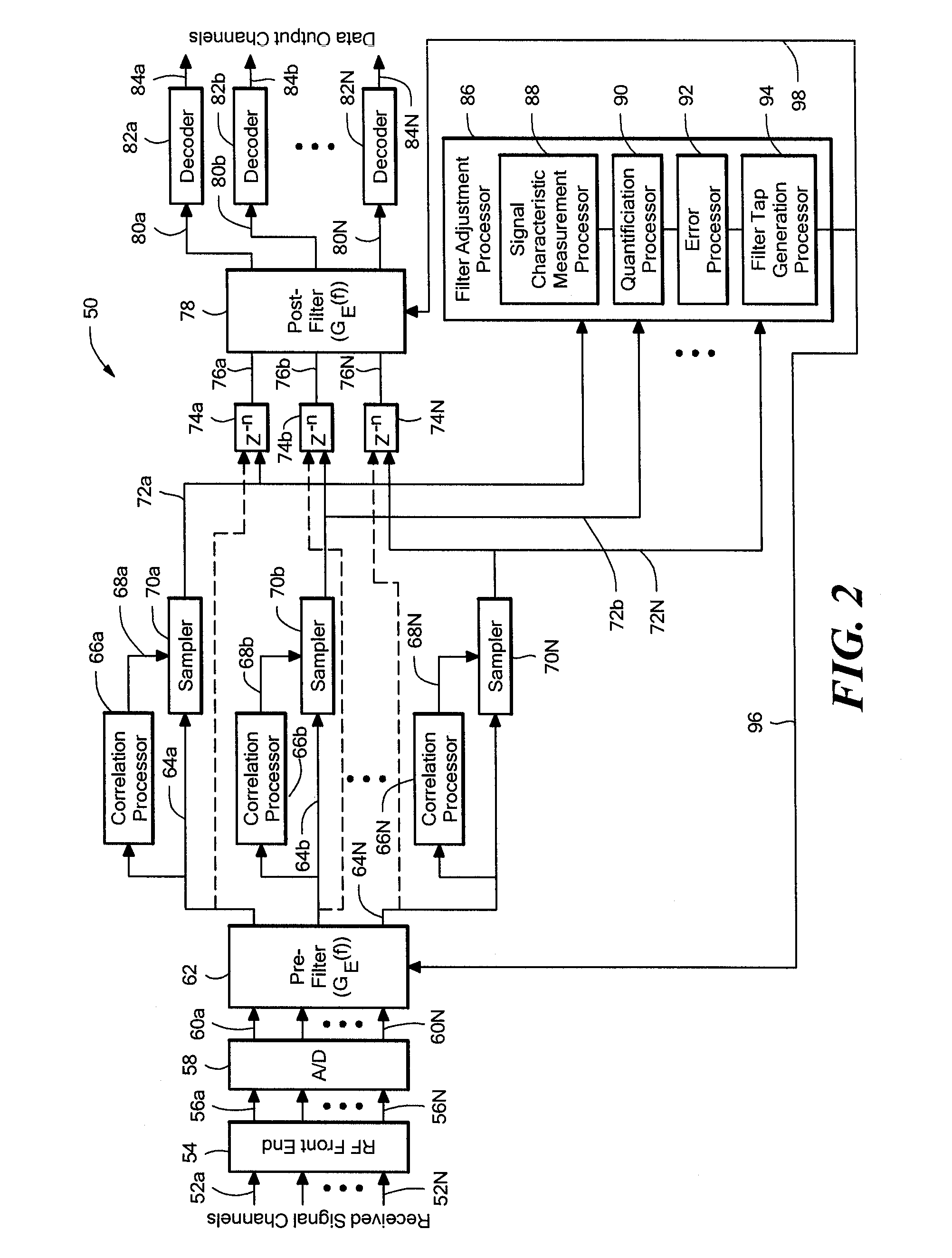
[0037]Before describing the present invention, some introductory concepts and terminology are explained. As used herein, the term “replica correlation” is used to describe a correlation of a signal with a “replica signal.” The term “replica signal” is used herein to describe a predetermined signal that is representative of a predetermined portion of a perfect received signal, i.e., a received signal that has not experienced any affect from a propagation channel. It will be understood that when the replica signal aligns in time during the replica correlation with the predetermined portion of a received signal, an output of the replica correlation has a high value, indicative of a signal match.

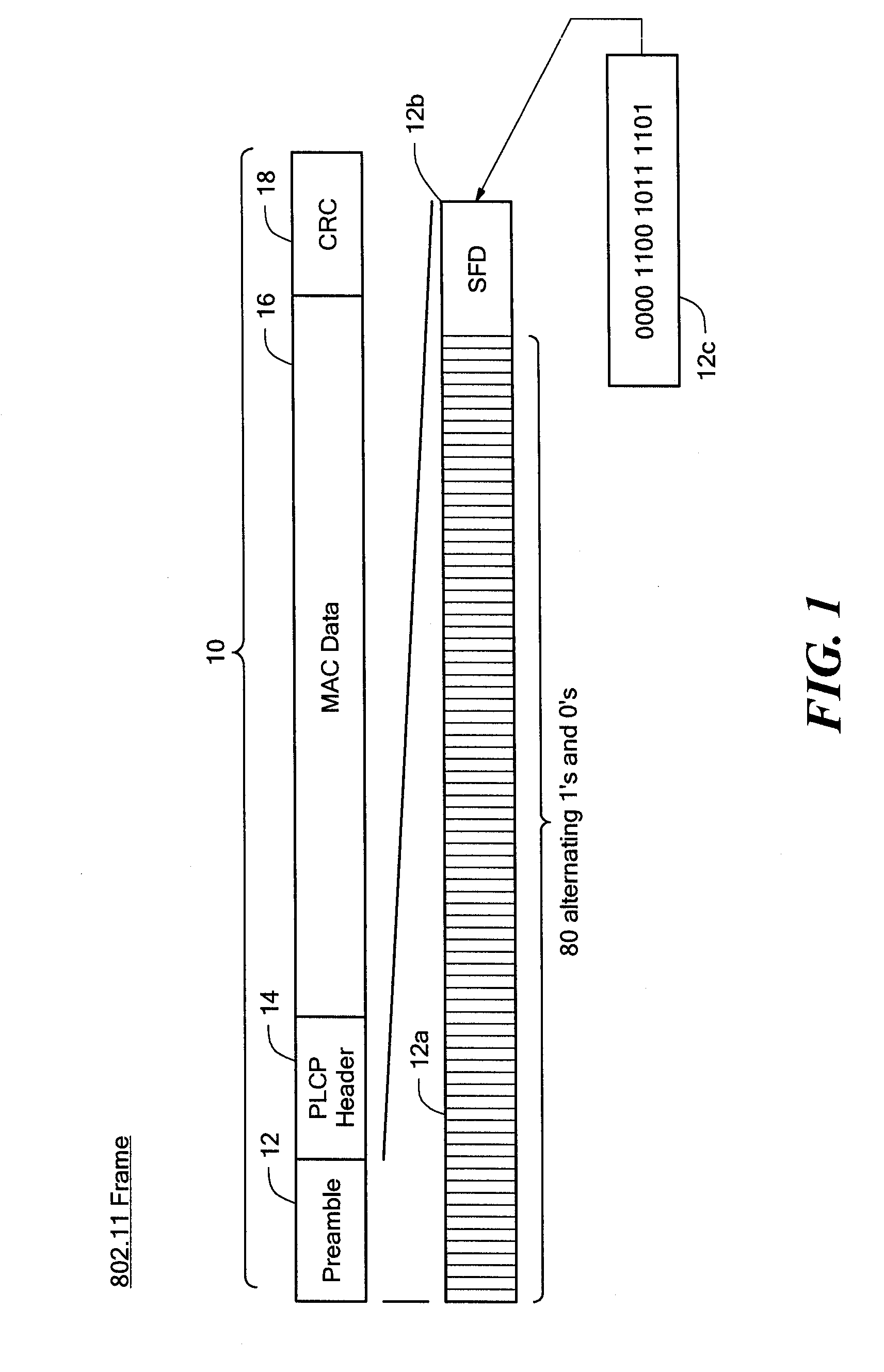
[0038]As used herein, the term “common digital signal” or simply “common signal” refers to a digital pattern of bits that occurs in each one of a plurality of digital packets, or in a large number of the digital packets.

[0039]While some examples of systems and methods used to characterize and to...


PUM


Abstract

In accordance with the present invention, a method of processing a signal is described that includes receiving a signal having an encoded digital packet, wherein the digital packet includes packet data and a packet frame, wherein the packet frame includes a common digital signal that is common to each one of a plurality of digital packets. The method further includes sampling a signal associated with the received signal to provide a sampled signal. The method further includes performing a channel characterization by contrasting a signal representative of the sampled signal with a signal representative of the common digital signal. A corresponding system is also described.

Description

FIELD OF THE INVENTION[0001]This invention relates generally to data communications and, more particularly, to a method and system for data channel characterization used in data communications.BACKGROUND OF THE INVENTION[0002]It is known that transmission of a digital signal through a medium, whether wired or wireless, can result in the digital signal becoming distorted due to affects of the medium. Digital signals transmitted though a wireless medium (i.e., wireless signals) can be distorted due to effects of multipath fading, magnitude response, and phase response of the wireless medium. Digital signals transmitted though a wire medium (i.e., wired signals) can also be distorted due to effects of magnitude response and phase response of the wired medium. Distortion of a digital signal can lead to loss of data, or data that is not properly interpreted by a receiver of the digital signal.[0003]A variety of methods of signal coding have been developed to address the above issues, par...

Claims


Application Information

Patent Timeline
IPC IPC(8): H04B17/00
CPCH04L25/0224H04L27/2647H04L25/03076H04L25/03057
Inventor WURZBACH, JAMES A.SHIELDS, STEVEN E.MANZI, DAVID G.
Owner RAYTHEON CO
Why Eureka
Eureka Blog
Learn More