Flexible display apparatus

Active Publication Date: 2008-07-31
CANON KK
View PDF7 Cites 16 Cited by
  • Summary
  • Abstract
  • Description
  • Claims
  • Application Information

AI Technical Summary

Benefits of technology

[0011]An object of the present invention is to provide a flexible display apparatus in which a surface located on a light emitting surface side can be prevented from damage caused by contact between the surfac

Problems solved by technology

The flexible display apparatus has a large screen, but is thin and light in weight, so the apparatus can be rolled up or bent.
However, in the flexible display apparatus, there arise problems involving dropping or impact while being carried and friction or wearing between contact surfaces thereof while being rolled up or bent for storage, which do not occur in the conventional display apparatuses.
However, even when the glass base film is thinned, there is a problem with respect to the impact resistance c

Method used


Image

  • Flexible display apparatus
  • Flexible display apparatus
  • Flexible display apparatus

Examples


Example

EXAMPLE 1

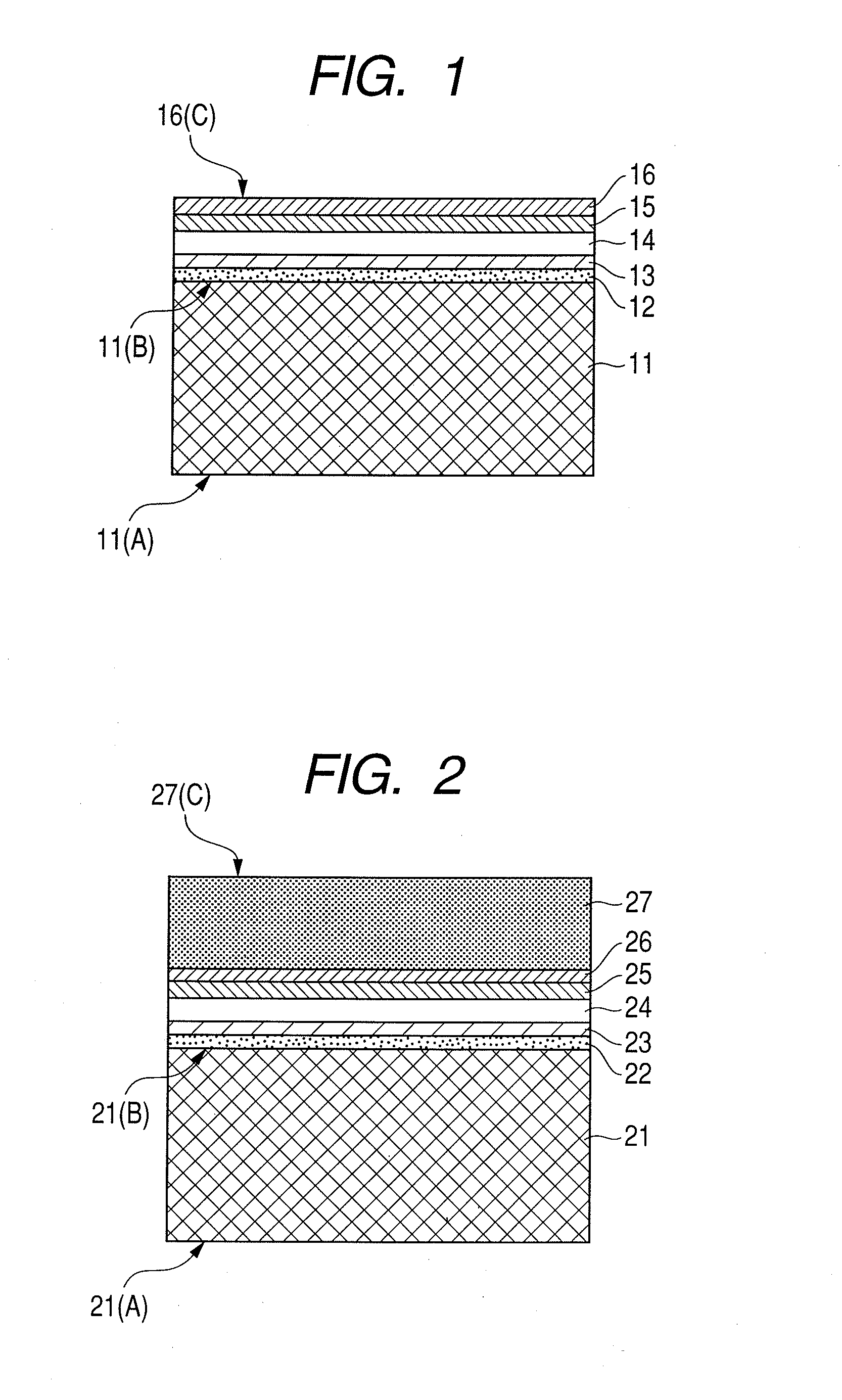
[0040]FIG. 2 illustrates a structure of a flexible display apparatus according to a first example of the present invention.

[0041]A base film 21 was a PES film (approximately 30 inches in diagonal size). A barrier layer which is a laminate of silicon nitride (SiN) thin films was formed on both surfaces of the base film 21 at a thickness of 0.5 μm.

[0042]A thickness of the PES film (hereinafter, also expressed by the same reference numeral 21 as that of the base film) 21 was 100 μm including a thickness of each of the barrier layers. A Young's modulus of the PES film 21 was 2,300 MPa and a light weight tear strength thereof was 2.0 MPa. A Vickers hardness of a lower surface 21(A) of the PES film 21 was 150. A surface roughness Ra of the lower surface 21(A) of the PES film 21 was 1.5 nm and a surface roughness Ra of an upper surface 21(B) thereof was 0.6 nm.

[0043]An SiO2 film was formed as an insulating layer 22 on the PES film 21 at a thickness of 500 nm by sputtering. A Cr th...

Example

[0048]Example 2 was identical to Example 1 except for that a PC film was used instead of the PES film located on the rear surface. This example will be described with reference to FIG. 2.

[0049]A barrier layer which is a laminate of silicon nitride (SiN) thin films was formed on both surfaces of the PC film (approximately 30 inches in diagonal size) of the base film 21 at a thickness of 0.5 μm.

[0050]A thickness of the PC film (hereinafter, also expressed by the same reference numeral 21 as that of the base film) 21 was 125 μm including a thickness of each of the barrier layers. A Young's modulus of the PC film 21 was 1,800 MPa and a light weight tear strength thereof was 1.8 MPa. A Vickers hardness of a lower surface 21(A) of the PC film 21 was 100. A surface roughness Ra of the lower surface 21(A) of the PC film 21 was 3.5 nm and a surface roughness Ra of an upper surface 21(B) thereof was 0.8 nm.

[0051]The display apparatus manufactured in this example was of the top emission type a...

Example

EXAMPLE 3

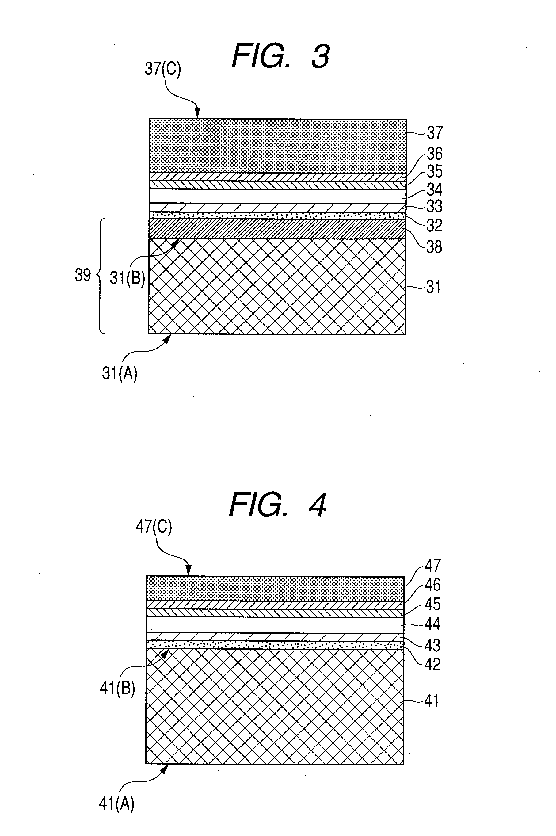
[0054]FIG. 3 illustrates a structure of a flexible apparatus according to a third example of the present invention.

[0055]A base film 31 was a PC film (approximately 30 inches in diagonal size). Barrier layers were not formed. A thickness of the PC film (hereinafter, also expressed by the same reference numeral 31 as that of the base film) 31 was 100 μm. A Young's modulus of the PC film 31 was 1,800 MPa and a light weight tear strength thereof was 1.8 MPa. A Vickers hardness of a lower surface 31(A) of the PC film 31 was 100. A surface roughness Ra of the lower surface 31(A) of the PC film 31 was 3.0 nm and a surface roughness Ra of an upper surface 31(B) thereof was 0.5 nm. A metal film 38 (10 μm in thickness) of SUS was formed on the PC film 31 by plating to construct a laminated composite base film 39 in which the PC film 31 and the metal film 38 were stacked.

[0056]An SiO2 film was formed as an insulating layer 32 on the base film 39 at a thickness of 500 nm by sputtering...


PUM

PropertyMeasurementUnit
Sizeaaaaaaaaaa
Flexibilityaaaaaaaaaa
Hardnessaaaaaaaaaa

Abstract

Provided is a flexible display apparatus in which a surface located on a light emitting surface side thereof can be prevented from damage caused by contact between the surface located on the light emitting surface side and a surface located on a rear surface side while the flexible display apparatus is rolled up in any size to be stored, thereby easily being stored in a small size. The flexible display apparatus has a light emitting device formed on a flexible base film and is rolled up so that the surface located on the light emitting surface side is brought into contact with the surface located on the rear surface side at the time of storage. A hardness of the surface located on the light emitting surface side is higher than a hardness of the surface located on the rear surface side.

Description

BACKGROUND OF THE INVENTION[0001]1. Field of the Invention[0002]The present invention relates to a flexible display apparatus (hereinafter, also simply referred to as a display apparatus) which is thin, light in weight, and large in screen size. In particular, the present invention relates to a display apparatus which can be rolled up or bent (folded) to be stored.[0003]2. Description of the Related Art[0004]Currently, the demands for thin display apparatuses represented by a liquid crystal display (LCD) and an organic electroluminescence (EL) display has been rapidly increasing. However, further reductions in thickness and weight have been required in the market. It is desired to realize a flexible display apparatus in the near future. The flexible display apparatus has a large screen, but is thin and light in weight, so the apparatus can be rolled up or bent. Therefore, the flexible display apparatus can be easily held and carried. However, in the flexible display apparatus, there...

Claims


Application Information

Patent Timeline
IPC IPC(8): B32B9/00B32B7/022
CPCB32B7/02H01L51/0097H01L51/52Y10T428/31H01L2251/5338Y02E10/549H01L51/5237B32B7/022H10K77/111H10K50/80H10K50/844H10K2102/311
Inventor HASHIMOTO, MORIMI
Owner CANON KK
Why Eureka
Try Eureka