Locking intramedullary jig

a technology of locking and intramedullary jigs, applied in the field of alignment jigs, can solve the problems of slipping, affecting the adjustment function, and the amount of torque that can be applied, and achieves the effect of precise adjustment and easy adjustment of the adjustment and locking function for the user

Inactive Publication Date: 2008-07-31
HOWMEDICA OSTEONICS CORP
View PDF18 Cites 15 Cited by
  • Summary
  • Abstract
  • Description
  • Claims
  • Application Information

AI Technical Summary

Benefits of technology

[0010]Another advantage of the present invention is that that a surgeon can detect through tactile feedback the precise amount of flexion-extension or anterior-posterior degrees that has been adjusted without relying on visual scribed lines. As a result of a spring-loaded shuttle, each degree being adjusted results in a detectable change in the force that is applied to rotate the jig. Once an adjustment is made, the jig will remain at this setting upon the release of the locking button, making the adjustment and locking function very easy for the user. A spring loaded wedge-like toothed shuttle is used to lockingly engage a ratchet on angle adjustor when the button is released. When the release button is pushed in then the shuttle teeth can ride over the teeth of ratchet. An added benefit of the spring-loaded shuttle is that with each degree of adjustment, an audible click is produced, thereby allowing the surgeon to make precise adjustments based on audible feedback.
[0011]These and other advantages of the present invention are provided by a locking intramedullary jig for use in bone resection surgery which jig mounts on an axially extending intramedullary rod, a trial stem, or intramedullary reamer for insertion into the medullary canal of a long bone such as a tibia or femur. The jig includes a slide block mounted on the intramedullary rod for movement along the rod in an axial direction. On the femur or tibia this is the proximal-distal direction. The slide block has a pivot point at one end thereof and a toothed portion and a second end thereof. A first rotating body is pivotally coupled to the pivot point on the slide block for rotation about a first axis generally perpendicular to the axis of the rod. The rotating body includes a toothed locking member or pawl moveably mounted thereon for releasable locking engagement with the toothed portion on the slide block. A bone resection guide is coupled to the first rotating body either directly or indirectly via a second rotating body.
[0012]The first rotating body of the jig includes a spring biased shaft mounted thereon with a first end engagable with the toothed locking member or pawl for moving the toothed locking member relative to the first rotating body into locking engagement with the toothed portion on the slide block. The spring biased shaft is moveable against the spring to a position which allows movement of the teeth on the toothed locking member away from the teeth on the slide block toothed portion to permit relative movement therebetween. This movement of the teeth away from one another can be limited so as to allow the teeth to slide up and over one another as the angle between the slide block and first rotating body about the pivot point changes. This produces the tactile and audible feedback.
[0013]Preferably, the jig has a second body with a rotating body part rotatably coupled to the first rotating body and a non-rotatable part fixed with respect to the first rotating body. The rotating part of the second body has a bone resection guide mounted thereon. The second body has a non-rotatable tooth portion mounted on the non-rotatable part and a rotatable portion coupled to the bone resection guide. The rotatable portion of the second body has a moveable locking pawl with the toothed portion for releasable locking engagement with a non-rotatable toothed portion of the second body. The rotating part of the second body includes a spring biased shaft mounted thereon with a first end engagable with the toothed locking pawl on the rotatable part. The shaft is spring biased for moving the toothed locking pawl into engagement with the non-rotatable toothed portion thereon. The spring biased shaft including the locking pawl is moveable against the spring to a position which allows movement of the teeth of the locking pawl away from the teeth on the non-rotatable toothed portion of the second body in a manner similar to that described above with regard to the first rotating body.
[0014]When used in connection with the femur or tibia, the cutting jig is mounted on an intramedullary rod (IM) which extends along the mechanical axis of either the tibia or femur which axis extends in a generally proximal-distal direction. Thus, the first rotating body rotatably coupled to the slide block mounted on the IM rod, trial stem, or reamer rotates about a medial-lateral axis. The rotating part of the second body portion then rotates about a generally anterior-posterior axis. Thus, the movement of the first body portion with respect to the slide block sets the flexion extension angle of the proximal tibia or distal femur and the rotating part of the second body sets the varus-valgus angle of the proximal cut on the tibia or the distal cut on the femur.

Problems solved by technology

A drawback of some of these instruments is that once varus-valgus and flexion-extension adjustments are made and locked in place, this alignment setting can slip during the subsequent pinning of the cutting guide to the proximal tibia.
Slippage may occur because the amount of torque that can be applied by hand to a knob of limited size, and with slippery gloves is somewhat limited.
Additionally, if the jig remains in place during the cutting operation, as is usual in revision surgery, the vibration caused by the saw may loosen the screws.

Method used


Image

  • Locking intramedullary jig
  • Locking intramedullary jig
  • Locking intramedullary jig

Examples


Embodiment Construction

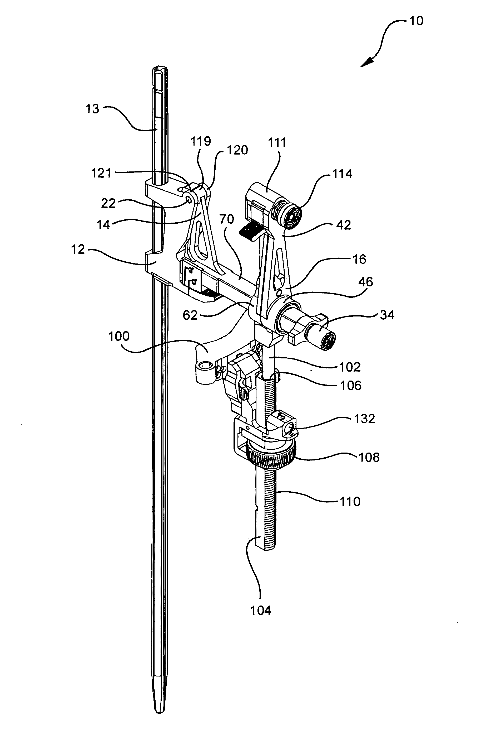
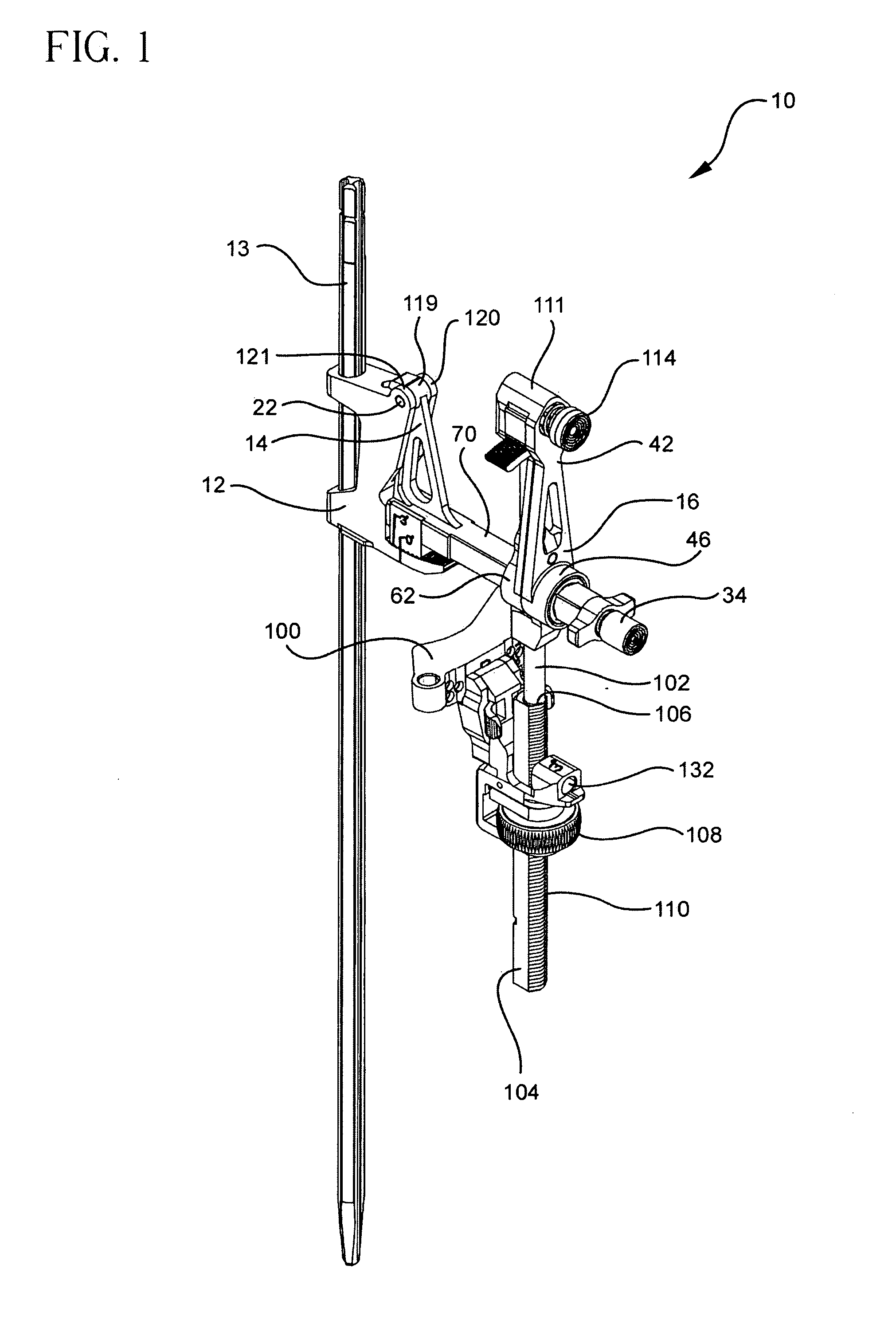
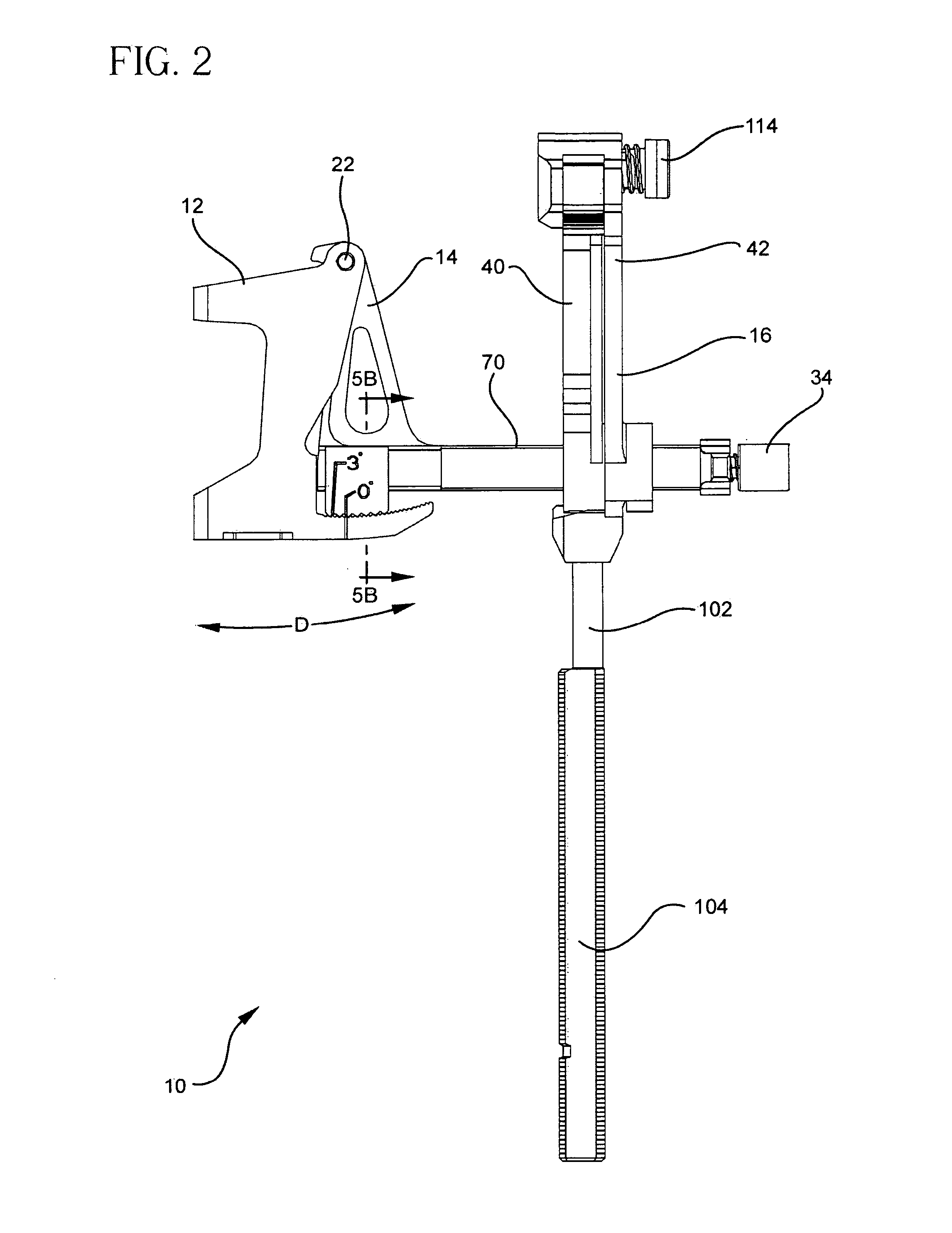
[0024]Referring to FIGS. 1 to 4 there is shown the tibial jig of the present invention generally denoted as 10. Jig 10 consists of an assembly containing three main functional elements: a main anchoring block 12, which connects to an IM rod 13 via bore 18 for sliding movement therealong. A first rotatable body or arm 14 is pivotally coupled to block 12 to adjust flexion-extension settings and a second body or arm 16 which includes a rotating part 42. Rotatable part 42 is coupled to slide block 12 via body 14 to adjust varus-valgus settings. Body 16 may be connected, either directly or indirectly via body part 14 to slide block 12. IM rod 13 is inserted into the medullary canal of a long bone such as the tibia (not shown) in a standard manner.

[0025]Cutting jig 10 further includes a cutting guide block 100 mounted thereon for vertical, i.e. proximal-distal movement with respect to a rod 104 mounted on body part 16. Block 100 is slidably adjusted along the length of a rod 104 and can b...


PUM


Abstract

A locking intramedullary alignment jig for use in bone resection, especially for the proximal tibial has an axially extending intramedullary rod for insertion into the medullary canal of the tibia. A slidable anchoring block is mounted on the rod for movement along the rod in the axial direction, which on the tibia is the proximal-distal direction. The anchoring block has a pivot point at one end thereof and a tooth portion at a second end thereof. A first rotating body is pivotally coupled to the pivot point on the anchoring block for rotation about a first axis. The rotating body includes a toothed locking member for releasable locking engagement with the toothed portion the anchoring block. A second rotating body, including a bone resection guide is connected to the first rotating body. Movement of the first and second rotating bodies allow rotation of the resection guide in both the flexion-extension and varus-valgus directions.

Description

CROSS-REFERENCE TO RELATED APPLICATIONS[0001]This application is a continuation of U.S. application Ser. No. 11 / 060,154, filed on Feb. 17, 2005, the disclosure of which is incorporated herein by reference.BACKGROUND OF THE INVENTION[0002]This invention relates to an alignment jig used to place and align a cutting guide in order to make a transverse cut on the tibia and / or femur.[0003]Intramedullary instruments are used by surgeons to place and subsequently align a cutting guide on a tibia or femur to a specific flexion-extension and varus-valgus angle with respect to the mechanical axis of the tibia or femur. Once the cutting guide is aligned to the desired settings, it is pinned to the bone for stability and used to guide a saw blade to make a transverse cut on the bone as required in total knee replacement surgery. The transverse cut would be on the proximal tibia or distal femur.[0004]A drawback of some of these instruments is that once varus-valgus and flexion-extension adjustme...

Claims


Application Information

Patent Timeline
Patent Type & Authority Applications(United States)
IPC IPC(8): A61B17/58A61F5/00
CPCA61B17/157A61B17/155
Inventor COLLAZO, CARLOS E.
Owner HOWMEDICA OSTEONICS CORP
Why Eureka
Try Eureka