Contralateral insertion method to treat herniation with device using visualization components

a technology of visualization components and insertion methods, applied in the field of flexible surgical cutting devices, can solve the problems of annulus tending to thicken, reducing the ability of elastic deformation under load, and drying out of the nucleus and becoming smaller and compressed

Inactive Publication Date: 2008-07-31
LAURIMED
View PDF102 Cites 50 Cited by
  • Summary
  • Abstract
  • Description
  • Claims
  • Application Information

AI Technical Summary

Benefits of technology

[0090]These and other aspects of the invention will become apparent to those persons skilled in the art upon reading the details of the invention as more fully described below.

Problems solved by technology

The proteoglycan and water from within the nucleus decreases which in turn results in the nucleus drying out and becoming smaller and compressed.
Additionally, the annulus tends to thicken, desiccate, and become more rigid, lessening its ability to elastically deform under load and making it susceptible to disc fissures.
Additionally, biochemicals contained within the nucleus pulposus may escape through the annulus causing inflammation and irritating adjacent nerves.
However, if conservative therapy offers no improvement then surgery is recommended.
However, minimally invasive techniques have been rapidly replacing open surgery in treating herniated discs.
However, as illustrated in FIGS. 1A and 1B, these prior art devices are typically rigid and therefore, only able to access the center of the nucleus and remove material along a linear path from the access point to the center of the nucleus (1).
As a result, the tissue removal is not performed at the site of the injury and thereby has limited effectiveness.
Furthermore, the rigid devices are typically able to treat only the L4-L5 disc and not the L5-S1 disc that is commonly the source of patient discomfort.
However, this direct approach to the disc herniation results in further injury to the already weakened disc annulus, thereby increasing the likelihood of subsequent herniations.
Therefore, the above methods are unable to access and treat most herniations at the specific site of injury.
As such, the above methods are designed to merely remove a portion of the nucleus pulposus within the center of the nucleus but do not specifically remove material from within the site of injury.

Method used


Image

  • Contralateral insertion method to treat herniation with device using visualization components
  • Contralateral insertion method to treat herniation with device using visualization components
  • Contralateral insertion method to treat herniation with device using visualization components

Examples


example 1

Indirect Visualization

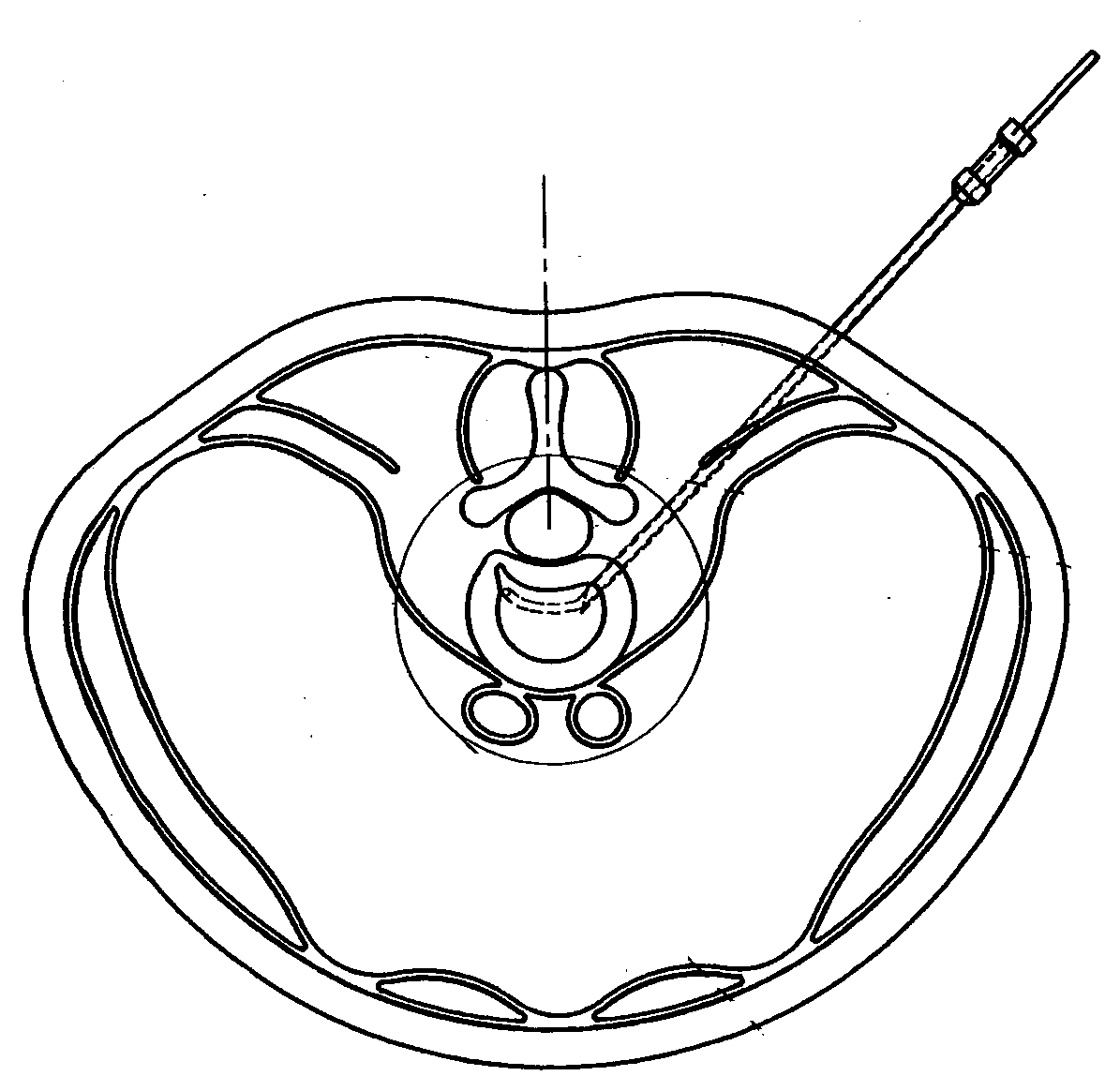
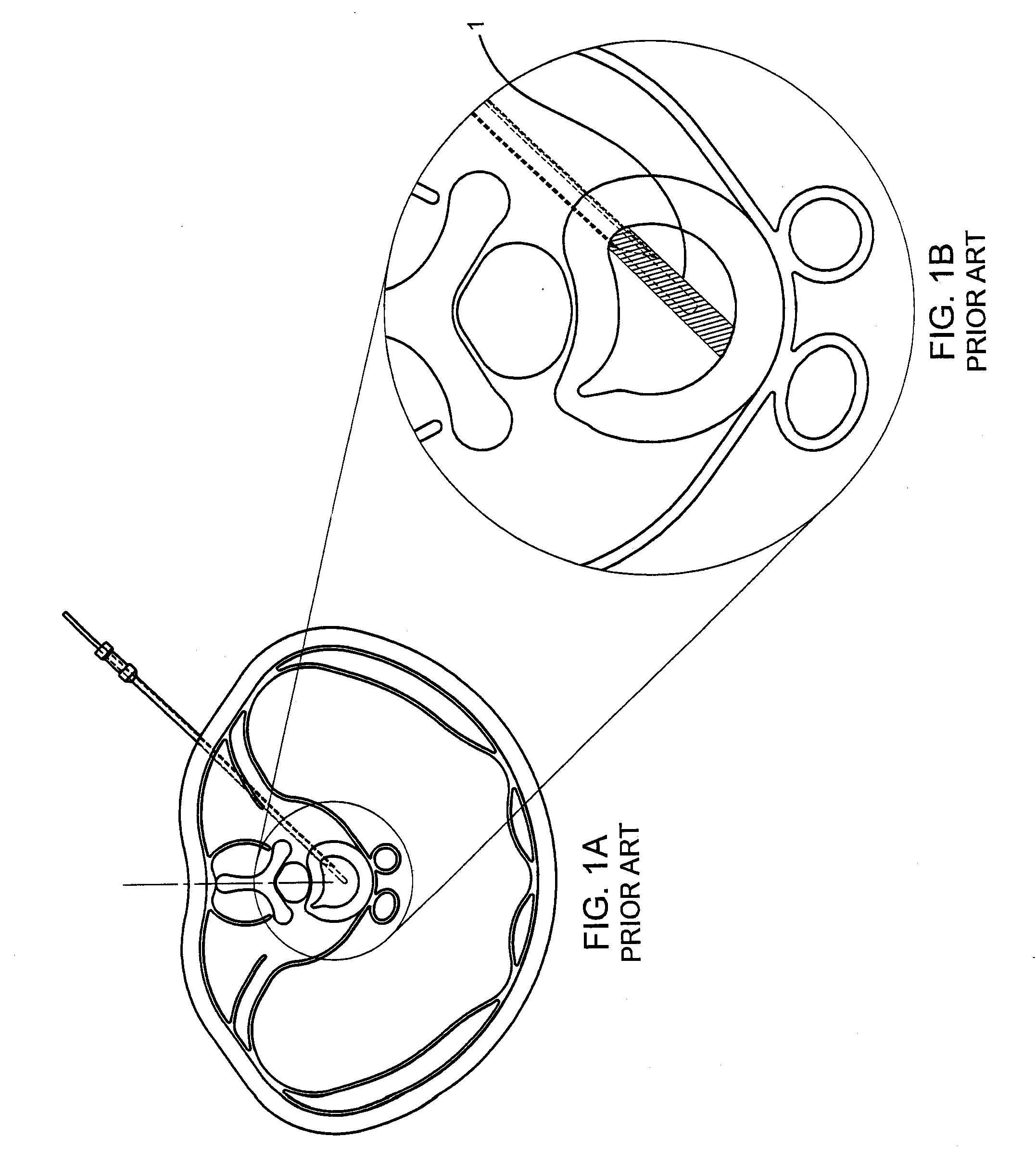
[0169]In general, a patient is examined and diagnosed with a herniated disc. Imaging technology such as MRI or an X-ray device is used to locate the position of the herniated disc. An introducer such as a hypodermic needle is provided that is inserted in a patient's body so that its distal end creates a small annular opening leading to the nucleus pulposus. A guide wire is slid into position within and through the introducer lumen so that a distal tip of the guide wire is positioned at the selected location within the nucleus by advancing or retracing the guide wire in the introducer lumen and optionally twisting the proximal end of the guide wire to precisely navigate the guide wire. A plurality of Guide Wires with different curvatures may be provided that enable the operator to navigate to precise locations within the nucleus pulposus.

[0170]A small incision is then made in the patient's skin and subcutaneous tissue which facilitates access of a dilator sheath...

example 2

[0174]In another exemplary embodiment for treating a herniated disc, a guide wire may be guided with fluoroscopic imaging to a position at the specific site of herniation. The guide wire may include markers which can be observed via X-ray and a bevel tip on the distal end and be made of a material having elastic or shape memory characteristics with a curvature at its' distal end. The guide wire may then be used to easily and accurately navigate to the herniation site to create a pathway for subsequent devices to follow to the herniation site. The Guide Wire may then be left in place to serve as a guide to the herniation site or subsequently inserted devices may follow the pathway left by the guide wire. The guide wire may be left in place or removed and the herniation site debulked as described in Example 1.

example 3

Direct Visualization

[0175]In general, a patient is examined and diagnosed with a herniated disc. Although direct visualization is to be used, imaging technology such as MRI or an X-ray device may still be used to locate the position of the herniated disc and the position may be marked on the patient.

[0176]An introducer such as a hypodermic needle is provided that is inserted in a patient's body so that its distal end creates an annular opening leading to the nucleus pulposus. A guide wire is slid into position within and through the introducer lumen so that a distal tip of the guide wire is positioned at the selected location within the nucleus by advancing or retracing the guide wire in the introducer lumen and optionally twisting the proximal end of the guide wire to precisely navigate the guide wire.

[0177]A small incision is then made in the patient's skin and subcutaneous tissue which facilitates access of a dilator sheath. The introducer is then removed and the dilator sheath i...


PUM


Abstract

A method for performing a selective discectomy is disclosed whereby a path for insertion of a tissue removal device is created by inserting a cannula with a flexible distal end position into an intervertebral disc by entering the nucleus at a point contralateral or anterolateral to a herniation site or entering anterior or anterolateral relative to the herniation site. The path is followed by a cutting device with a cutting window and either or both of the cannula or cutting device may be positioned at a site of herniation using all of any of control wires, a set of styli, viewable markings on a component and/or visualization devices.

Description

CROSS-REFERENCE[0001]This application claims the benefit of U.S. Provisional Application Nos. 60 / 886,860, filed Jan. 26, 2007; 60 / 887,997, filed Feb. 2, 2007; 60 / 892,498, filed Mar. 1, 2007; 60 / 896,226, filed Mar. 21, 2007; 60 / 945,521, filed Jun. 21, 2007; 60 / 945,518, filed Jun. 21, 2007; and 60 / 945,519, filed Jun. 21, 2007, which applications are incorporated herein by reference. This application further incorporates by reference patent applications filed on the same day herewith and identified as attorney docket numbers SAAL-005 and SAAL-007.FIELD OF THE INVENTION[0002]The present invention is drawn to a flexible surgical cutting device which is navigatable within a subject such as within the confines of the intervertebral disc and methods of using the subject devices for performing selective percutaneous discectomy.BACKGROUND OF THE INVENTION[0003]The intervertebral disc is composed of a thick outer ring of cartilage (annulus) and an inner gel-like substance (nucleus pulposus). T...

Claims


Application Information

Patent Timeline
Patent Type & Authority Applications(United States)
IPC IPC(8): A61B19/00A61B1/00A61B1/12
CPCA61B17/320783A61B2017/2905A61B2017/00867A61B2017/00261A61B17/3421A61B2017/003A61B90/37
Inventor SAAL, JEFFREY ALANSAAL, JOEL STUARTDUBOIS, BRIAN R.CHRISTIAN, JEFF
Owner LAURIMED
Why Eureka
Try Eureka