Process for producing holes

Inactive Publication Date: 2008-07-31
MTU AERO ENGINES GMBH
View PDF10 Cites 6 Cited by
  • Summary
  • Abstract
  • Description
  • Claims
  • Application Information

AI Technical Summary

Benefits of technology

[0010]Through the specified realization the quality of processing, and with it the quality of the holes, increases because the misalignment caused by the component tolerances is avoided and the drilled funnels are formed according to specification. Furthermore, drilling through the walls of the inner geometry due to the misalignment of the holes and/or the cores is avoided. Merging holes caus

Problems solved by technology

Tolerances of the outer geometry, e.g. in blade profiles, and of the inner geometry, e.g. in cavities or cores, as well as the inconsistency between them make process-stable production difficult.
Furthermore, process-stable production is made difficult because the tolerances of the outer surface cause shifting, twisting,

Method used


Image

  • Process for producing holes
  • Process for producing holes
  • Process for producing holes

Examples


Embodiment Construction

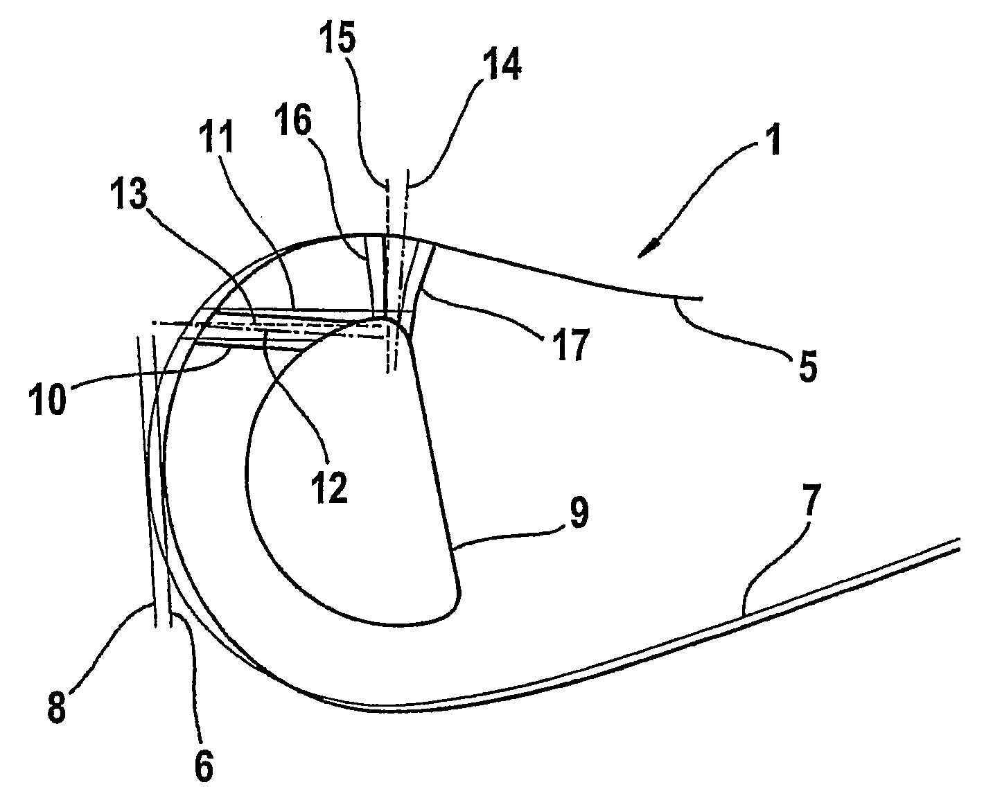
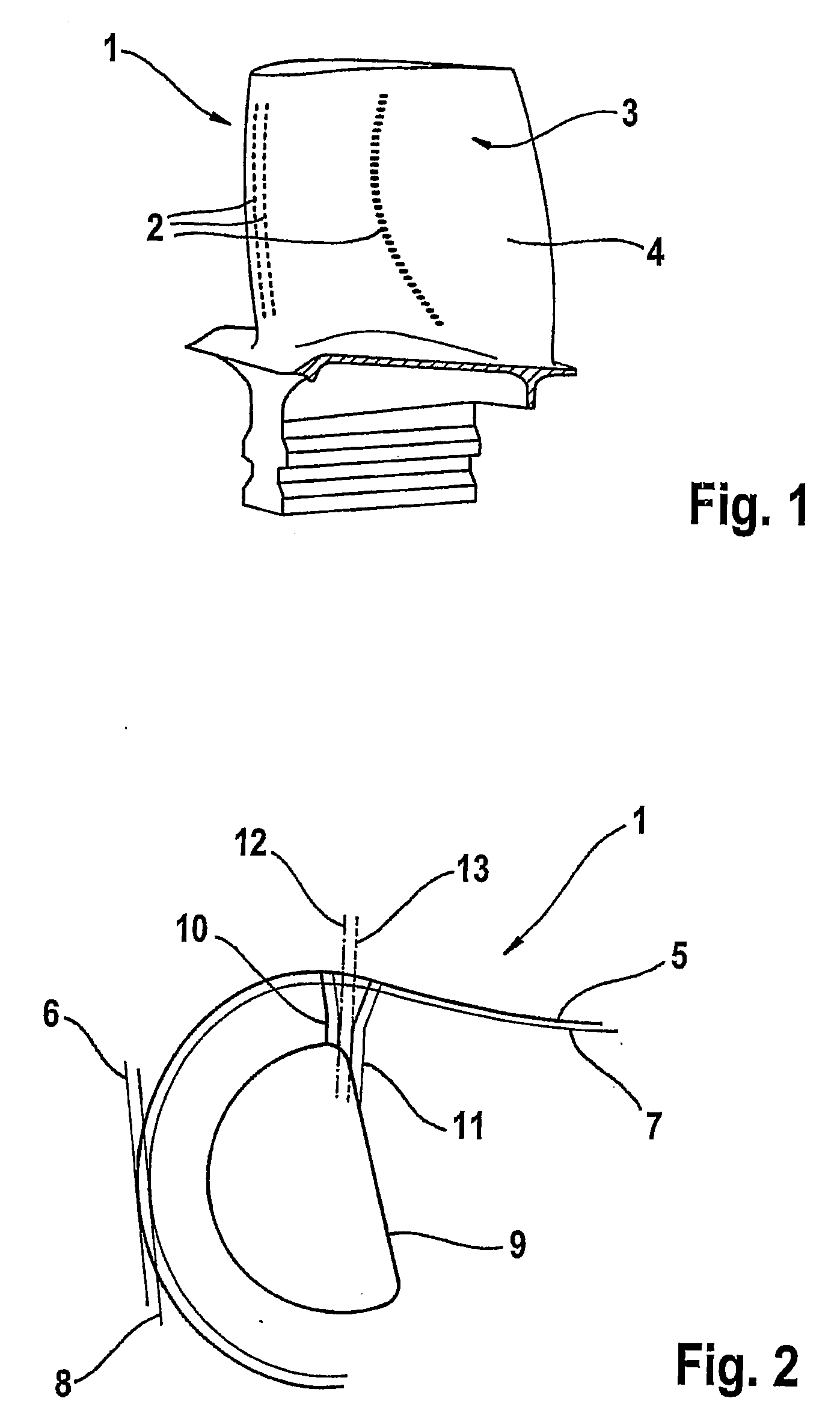
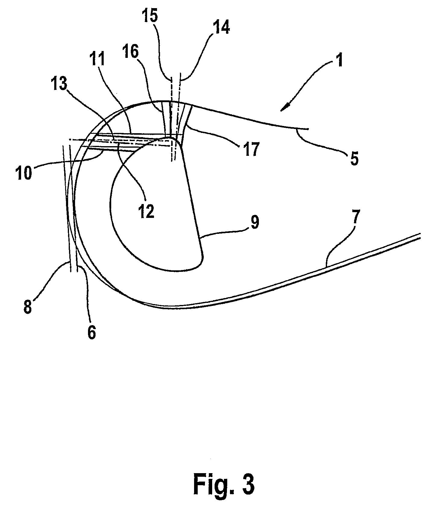
[0015]According to the presently described technology, a process for producing holes in a component, in particular of turbo engines, where each hole extends from a first surface at the exterior of the component to a second surface at the interior of the component, comprises the following steps:[0016]developing a 3-D model of the geometry of the component, at least for the area of the holes;[0017]adapting each hole on the basis of, the actual geometry of the component;[0018]generating a production program for each individual hole.

[0019]The production of cool air holes requires that the outer and inner geometries (cavities in the turbine blade) of the individual part are known. This is provided via a 3-D model of the individual component. A 3-D model can be a surface model or a volume model. A 3-D model can be developed via computer tomography (CT) but other processes are also conceivable. If the precision of the CT for the outer geometry is inadequate, then it is generated via an opt...


PUM

PropertyMeasurementUnit
Volumeaaaaaaaaaa
Areaaaaaaaaaaa
Depthaaaaaaaaaa

Abstract

A method of producing holes in a component, in particular of turbomachines, wherein each hole extends from a first, outer surface to a second, inner surface of the component and wherein the method has, for example, the following steps: producing a 3D model of the actual geometry of the component, at least for the region of the holes; adopting each hole on the basis of the actual geometry of the component; generating a production program for each individual hole. In this way, the process quality and with it the quality of the holes increases, because the offset of holes caused by component tolerances is avoided and the drilling funnels are formed according to specification. Furthermore, drilling defects on account of the offset of holes and/or cores can be avoided. Overlapping holes caused by component tolerances are likewise avoided.

Description

RELATED APPLICATIONS[0001]This application is a continuation of International Application No. PCT / DE2006 / 001497 (International Publication Number WO 2007 / 028355), having an International filing date of Aug. 26, 2006 entitled “Method of Producing Holes”. International Application No. PCT / DE / 2006 / 001497 claimed priority benefits, in turn, from German Patent Application No. 10 2005 042 270.5, filed Sep. 6, 2005. International Application No. PCT / DE / 2006 / 001497 is hereby incorporated by reference herein in its entirety.FEDERALLY SPONSORED RESEARCH OR DEVELOPMENT[0002][Not Applicable]MICROFICHE / COPYRIGHT REFERENCE[0003][Not Applicable]BACKGROUND OF THE INVENTION[0004]The present technology relates generally to a process for producing holes in a component, in particular in a turbo engine, where each hole extends from a first surface at the exterior of the component to a second surface at the interior of the component. Furthermore, a production arrangement for carrying out the process is s...

Claims


Application Information

Patent Timeline
IPC IPC(8): G06F19/00B23B35/00B23B39/00
CPCB23K26/383B23K26/388Y10T408/03Y10T408/08B23P2700/06B23K26/384B23K26/389G05B19/4099G05B19/402
Inventor KRIEGMAIR, JOSEF
Owner MTU AERO ENGINES GMBH
Why Eureka
Try Eureka