Facilitating recovery in a coordinated timing network

Active Publication Date: 2008-07-31
IBM CORP
View PDF38 Cites 38 Cited by
  • Summary
  • Abstract
  • Description
  • Claims
  • Application Information

AI Technical Summary

Benefits of technology

[0048]FIG. 26 depicts one example of a computer program produc

Problems solved by technology

This timer requires expensive dedicated timing links and a separate external box.
Networks, such as the Network Timing Protocol (NTP), provide time synchronization, but do not meet the accuracy requirements of high-end systems.
This is a problem for those syste

Method used


Image

  • Facilitating recovery in a coordinated timing network
  • Facilitating recovery in a coordinated timing network
  • Facilitating recovery in a coordinated timing network

Examples


Embodiment Construction

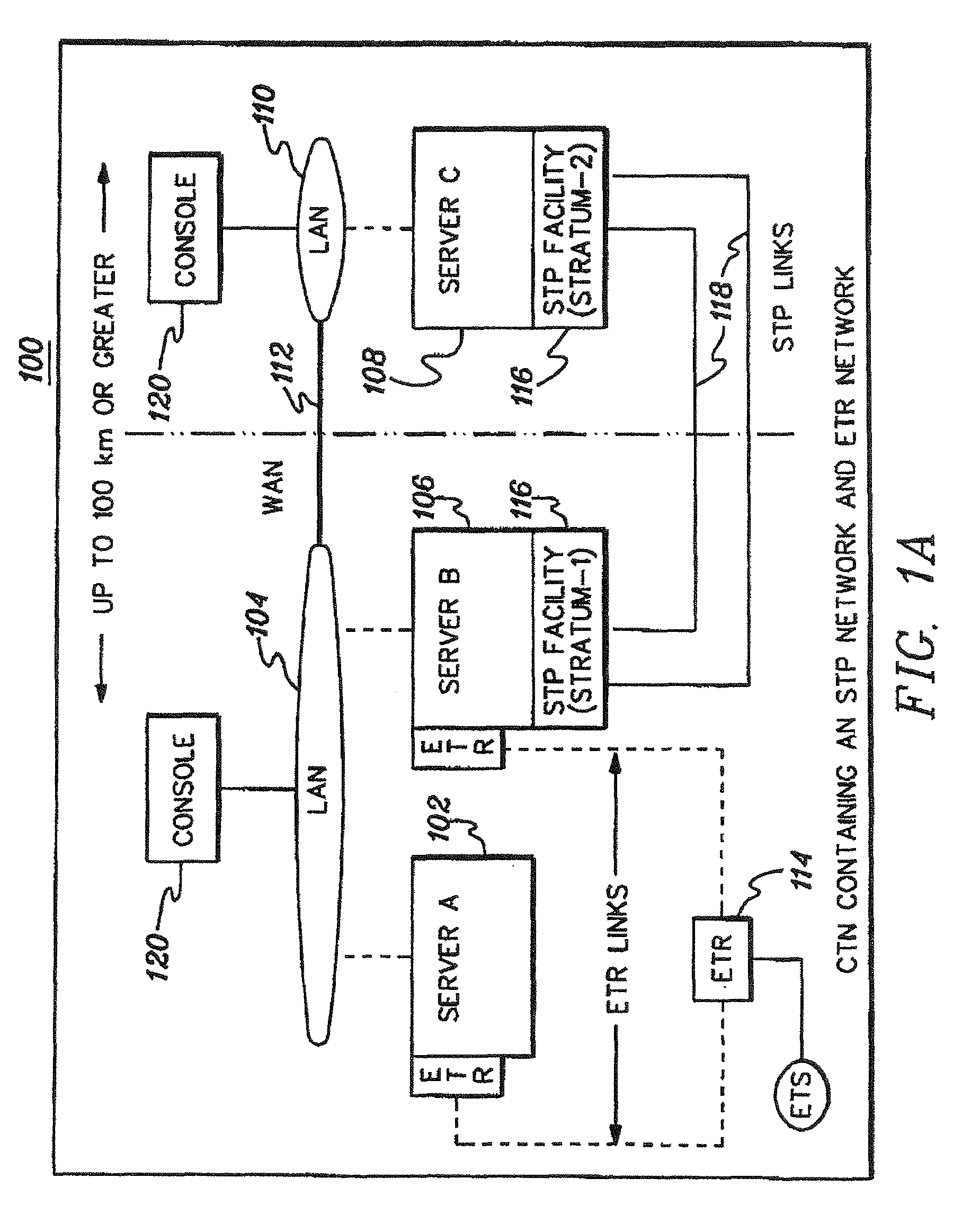
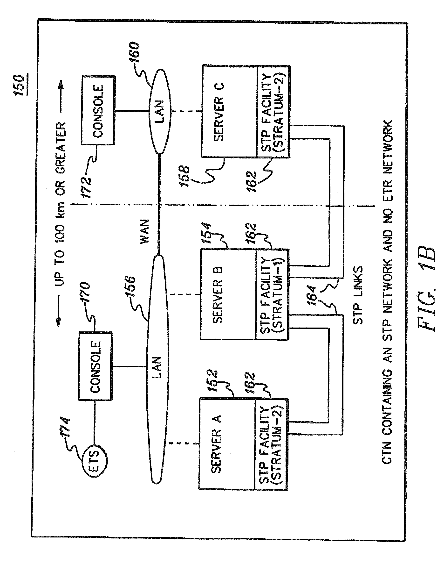
[0049]In accordance with an aspect of the present invention, a capability is provided for defining a stratum-1 configuration for a timing network that includes a single active stratum-1 server usable in ensuring that the servers in the network use the same primary reference time to synchronize their clocks. Thus, the servers in the network are synchronizing to the same root primary reference time and synchronization accuracy is not dependent on the quality of an external time source or of the existence of an external time source at the stratum-1 server.

[0050]In a further aspect of the present invention, the stratum-1 configuration is maintained in a stratum-1 configuration information block that is provided to the servers of the network, along with other information, which is used to ensure the integrity of the servers. Since each server in the network is aware of the identity of the stratum-1 server, servers that indicate they are synchronized to another stratum-1 server are not pe...


PUM


Abstract

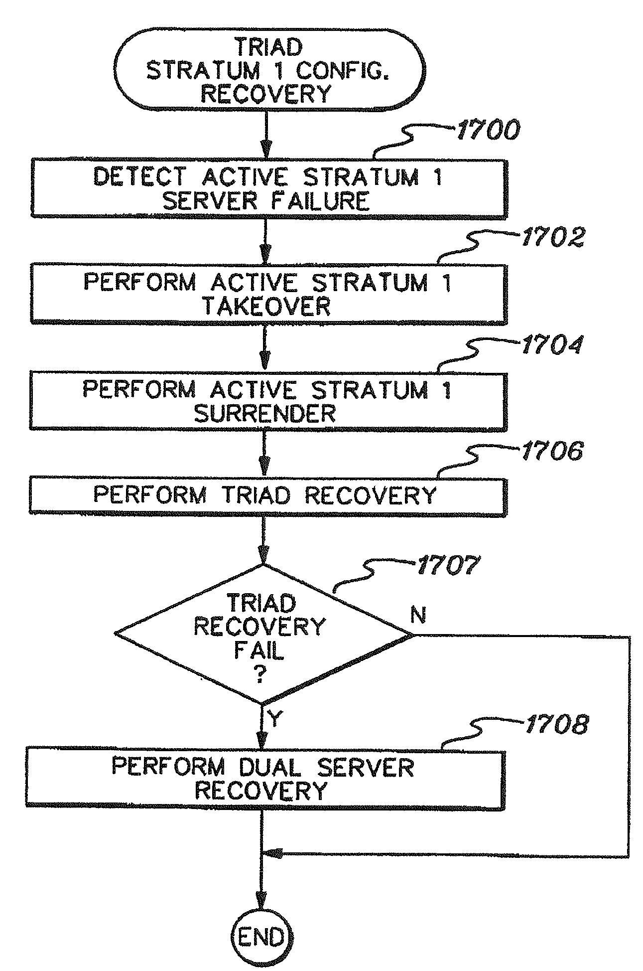
Recovery is provided in a timing network. A configuration is defined for that network, and in that configuration, an active primary server is identified that provides a clock source for the network. Additionally, an alternate server is identified that can perform the role of the active primary server, should the active primary server fail. In response to a failure of the primary server, the alternate server detects the failure and performs takeover of the primary server.

Description

CROSS-REFERENCE TO RELATED APPLICATIONS[0001]This application claims priority to U.S. Provisional Application No. 60 / 887,586, entitled “FACILITATING RECOVERY IN A COORDINATED TIMING NETWORK”, filed Jan. 31, 2007, which is hereby incorporated herein by reference in its entirety.[0002]This application also contains subject matter which is related to the subject matter of the following application, which is assigned to the same assignee as this application. The below listed application is hereby incorporated herein by reference in its entirety:[0003]“FACILITATING RECOVERY IN A COORDINATED TIMING NETWORK, AND METHODS THEREFOR” Carlson et al., U.S. Ser. No. ______, filed herewith.TECHNICAL FIELD [0004]This invention relates, in general, to time synchronization within and across a network of processing units, and in particular, to facilitating recovery within the network.BACKGROUND OF THE INVENTION[0005]For performance and data integrity, computing systems that access shared data, such as...

Claims


Application Information

Patent Timeline
IPC IPC(8): G06F11/14
CPCH04J3/0641H04J3/06
Inventor CARLSON, SCOTT M.CRABTREE, DONALDDAHLEN, DENNIS J.DHONDY, NOSHIR R.ELKO, DAVID A.SEVIGNY, DENISE M.SMITH, RONALD M.WHITNEY, DAVID E.WIERBOWSKI, JUDITH A.
Owner IBM CORP
Why Eureka
Try Eureka