Hinge structure having leaf portions with adjustable clamping force arm

a clamping force arm and hinge technology, applied in the field of hinge structures, can solve the problems of inability to adjust the compression force applied by the barrel against the pintle, association of the pintle with the barrel, and the prior art hinges of prior art, etc., to reduce the predetermined rolling friction, simple structure, and easy assembly

Inactive Publication Date: 2008-08-07
MITAC TECH CORP
View PDF7 Cites 15 Cited by
  • Summary
  • Abstract
  • Description
  • Claims
  • Application Information

AI Technical Summary

Benefits of technology

[0011]In addition to the advantages of having simple structure and easy to assemble, the hinge structure of the present invention is further characterized by having two leaf portions with an adjustable clamping force arm each. When the hinge structure has been used over a long time, and the contact areas between the barrel portion and the pintle are worn off to reduce the predetermined rolling friction between the barrel portion and the pintle, at least one clamping force adjusting element may be mounted to the clamping force arms on the two lea...

Problems solved by technology

There are some problems existed in the hinges of prior art.
Once the barrel is formed, it is impossible to adjust a compression force applied by the barrel against the pintle.
There is also problem in the association of the pintle with the barrel.
By doing this, a lo...

Method used


Image

  • Hinge structure having leaf portions with adjustable clamping force arm
  • Hinge structure having leaf portions with adjustable clamping force arm
  • Hinge structure having leaf portions with adjustable clamping force arm

Examples


Embodiment Construction

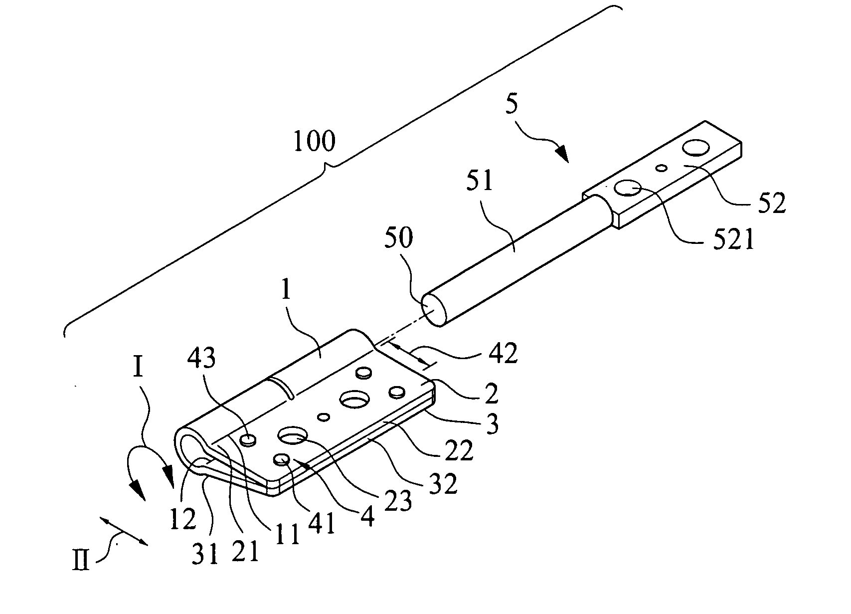
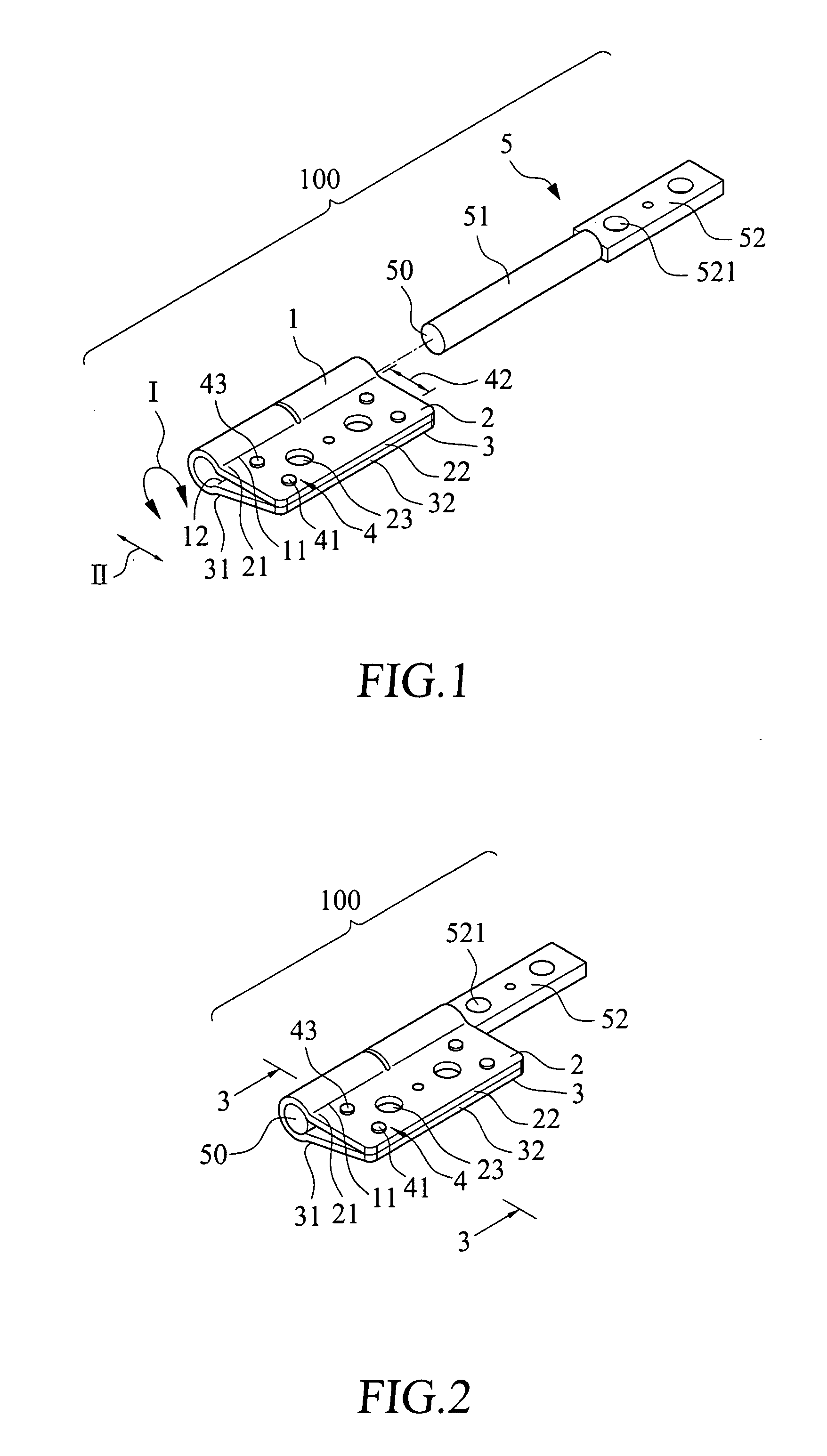
[0021]Please refer to FIGS. 1 and 2 that are exploded and assembled perspective views, respectively, of a hinge structure having leaf portions with adjustable clamping force arm according to a first embodiment of the present invention. As shown, the hinge structure in the first embodiment is generally denoted a reference numeral 100, and includes a barrel portion 1, a first leaf portion 2, a second leaf portion 3, and at least one leaf locating element 4.

[0022]The barrel portion 1 has a first edge 11 and a second edge 12 located opposite to the first edge 11. The barrel portion 1 is formed by extending from the first edge 11 in a circular direction I to the second edge 12, and accordingly, has a substantially C-shaped cross section.

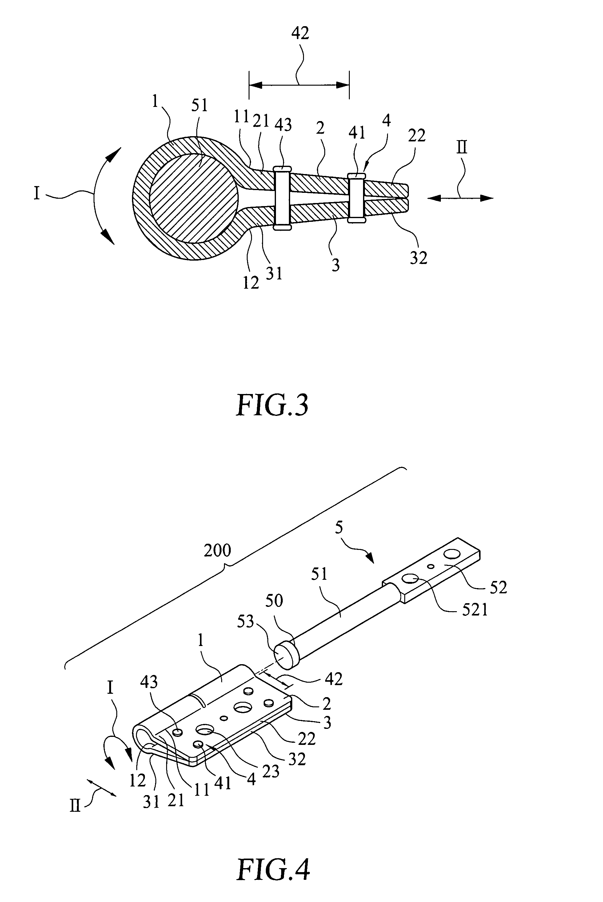
[0023]Please also refer to FIG. 3, which is a sectional view taken on line 3-3 of FIG. 2. The first leaf portion 2 has a root end 21 and a free end 22. The first leaf portion 2 is connected at the root end 21 to the first edge 11 of the barrel portion 1 w...


PUM


Abstract

A hinge structure having leaf portions with adjustable clamping force arm includes a leaf structure and a pintle. The leaf structure includes a C-shaped barrel portion, and a first and a second leaf portion connected to and extended from two opposite axial edges of the barrel portion. Free ends of the first and second leaf portions are bound together by at least one leaf locating element. With the leaf locating element functioning as a fulcrum, a clamping force arm section is defined on each leaf portion between the fulcrum and the barrel portion. The pintle is rotatably received in the barrel portion with a predetermined rolling friction existed between them. The predetermined rolling friction is adjustable through mounting at least one adjusting element to the two clamping force arm sections.

Description

FIELD OF THE INVENTION[0001]The present invention relates to a hinge structure, and more particularly to a hinge having leaf portions with adjustable clamping force. The hinge includes a C-shaped barrel portion and two leaf portions extended from two axial edges of the barrel portion. A pintle is rotatably received in the barrel portion. Free ends of the two leaf portions are tightened together with at least one leaf locating element, which functions as a fulcrum, so that a clamping force arm section is defined on each leaf portion between the fulcrum and the barrel portion to provide a predetermined rolling friction between the barrel portion and the pintle.BACKGROUND OF THE INVENTION[0002]Hinges are quite often used in various electric and electronic apparatus to connect two members of the apparatus, so that the two members are pivotally turnable about the hinges relative to one another. For example, a notebook computer uses hinges to pivotally connect a liquid crystal display (LC...

Claims


Application Information

Patent Timeline
IPC IPC(8): E05D7/00
CPCE05D11/082E05Y2201/21E05Y2201/25E05Y2201/26Y10T16/52E05Y2900/606G06F1/1616G06F1/1681H04M1/0216E05Y2201/266
Inventor CHAO, PO-TSUN
Owner MITAC TECH CORP
Why Eureka
Try Eureka